5 - 13 ELECTRICAL
GEM Service Manual November 2007
DRIVE AND POWER SYSTEM (Continued)
Step Action Yes No
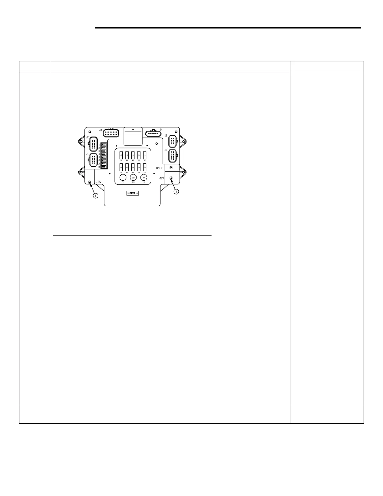
4 Remove the upper and lower dash panels and
locate the power signal distribution module
(PSDM). Measure the voltage on the PSDM at the
measuring points indicated.
Fig. 6 PSDM
1 - Measuring point
Is the voltage approximately 72 VDC?
Proceed to Step 5.
1. If voltage is
present, but less
than 70 VDC,
charge the
batteries.
2. Verify the Main
fuse for open
condition by
measuring the
voltage at the
fuse connection
at the PSDM
cable side (in the
battery
compartment). If
the fuse is open,
replace the fuse.
If the fuse opens
again, contact the
GEM Service
Department.
3. If no voltage is
present at the
Main fuse use the
Main Contactor
Circuit Diagram
and a voltmeter to
check all battery
connections.
4. If voltage is
present at the
main fuse, use
the Main
Contactor Circuit
Diagram and a
voltmeter to
check the wiring
connections and
the master
disconnect switch
up to the
measuring point.
5 Verify operation of relays. Unswitched 12 VDC
input. 72 VDC ground.
Proceed to Step 6.
Replace relays.
 Loading...