BRAKES 4 - 5
November 2007 GEM Service Manual
OPERATION
FRONT BRAKE ASSEMBLY
When applying the brake pedal, pedal pressure
forces the brake fluid through the brake line, from
the master cylinder to each caliper. This pressure
pushes the caliper piston out, causing the brake
pads to press against the brake rotor, which stops
the rotation of the rotor and wheel.
DESCRIPTION
The front brake assembly consists of a caliper,
rotor and brake pads. The rotor and caliper are
mounted to the steering knuckle. A half shaft (drive
shaft) engages splines on the spindle, and is
attached by a nut and washer.
REMOVAL
1. Raise and support the vehicle on a suitable
hoist.
2. Remove the hubcap.
3. Remove the tire and wheel assembly.
4. Disconnect the brake hose from the caliper.
Allow fluid to drain into suitable container for
disposal.
5. Remove the bolts and the brake caliper.
6. Remove the hub spacer plate.
7. Remove 15/16" drive shaft cotter pin and
retaining nut.
8. Remove the hub and rotor assembly.
9. Remove the four screws and the rotor
assembly.
INSTALLATION
1. Install the rotor on the hub and install the four
screws. Apply Loctite® 242 to the threads and
tighten the screws to 15 ft-lb.
2. Install the rotor and hub assembly onto the
vehicle.
3. Install and tighten snugly the 15/16" drive shaft
retaining nut and washer.
4. Install the hub spacer plate.
5. Install the brake caliper and tighten the bolts to
20 ft-lb.
6. Connect the brake hose to the caliper using
new washers. Tighten the bolt to 20 ft-lb.
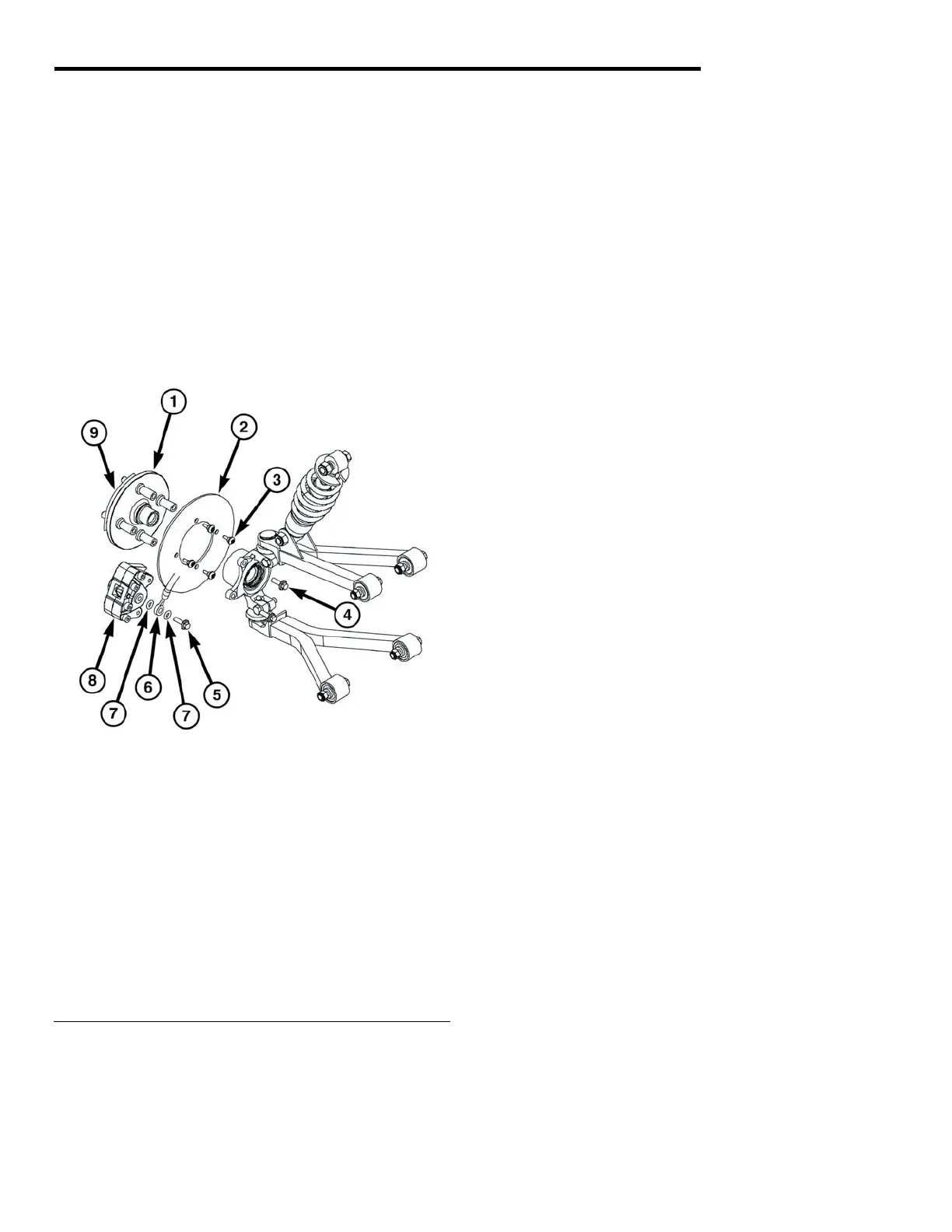
Fig 4 Front Brake Breakdown
(* indicates serviceable part)
7. Install the tire and wheel assembly. Tighten the
lug nuts to 65 ft-lb.
1 - Hub* 6 - Brake Line*
2 - Rotor* 7 - Brake Line Washer*
3 - Rotor Mounting Bolts* 8 - Front Brake Caliper
4 - Caliper Mounting Bolts* 9 - Spacer Plate*
5 - Brake Line Mounting Bolt*
8. Back off drive shaft retaining nut, apply Loctite®
242 and tighten to 65 ft-lb. Install the cotter pin.
9. Install the hubcap.
10. Bleed the brakes. See Brake Bleeding
instructions in this section.
 Loading...