4 - 2
Hardware Installation Guide for the Polycom SoundStructure C16, C12, C8, and SR12
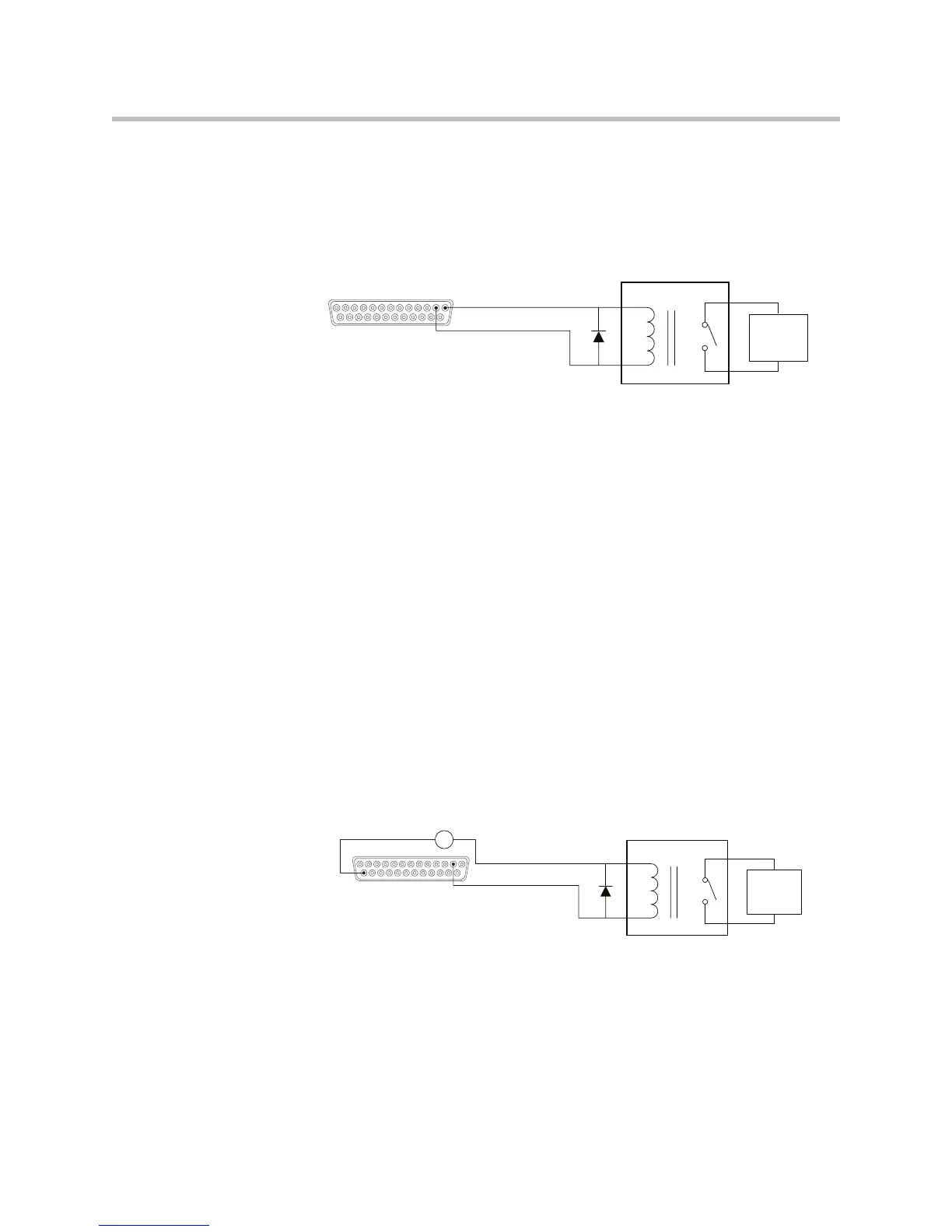
Logic Output
SoundStructure Powered Relay
Relays rated for +5 V or lower may be driven directly from the +5 V logic
connector pin 1 supply. Relays rated for more than +5 V will need an external
power supply as described in the next example.
When the logic output (Pin 2 in this example) is set on (high), current flows
from Pin 2 to ground and current that flows will energize the relay coil and
close the relay contact. When the logic output is set off (low), current will stop
flowing to the relay coil, causing the relay contact to open. A diode is
recommended to be placed in parallel with the relay to provide a path for the
discharge current of the magnetic coil of the relay. This current will discharge
over a very short period of time and a diode capable of handling a large
amount of surge current such as the IN4001 is recommended and is available
from several manufacturers.
This example circuit uses an Omron G5CA relay and the coil resistance is 125
ohms. Because of this coil resistance, an additional series resistor is not
required to limit the current from the 5 V supply to less than 500 mA in this
example.
Externally Powered Relay
SoundStructure can be used with externally powered relays when the
following conditions exist:
• The relay is DC powered.
• The DC voltage does not exceed 60 V.
External
Device to
be
Controlled
5 V Relay
Remote Control
Pin 1 : +5 V
Pin 2 : Logic Output 1
External
Device to
be
Controlled
12 V Relay
Remote Control
Pin 25 : Ground
External +12 V
Pin 2 : Logic Output 1
- +