INSTALLATION
VORTEX EF2201 Reference Manual 8 Technical Support: 800.932.2774
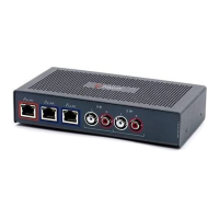
The following steps are typically used to set up the EF2201:
• Connect the EF B
US IN to EF BUS OUT on a Vortex echo canceller. This connec-
tion will provide both audio and remote control information to and from the Vor-
tex device.
• Connect the L
INE RJ11 jack to an analog telephone line.
• Connect the P
HONE RJ11 jack to an analog telephone set (optional).
• Connect the external power supply to the P
OWER SUPPLY INPUT jack of the
EF2201.
• Set the country code on the EF2201. By default the phone interface will be dis-
abled until you select a country code for the telephony interface. This can either
be done with the front panel LCD menu, or the RS-232 interface. The country
code only needs to be selected the first time or when the country of the installa-
tion is changed.
D
EVICE
ID
S
ON
THE
EF B
US
When considering which Device IDs can be used for which Vortex device, decide
how many devices have the ability to transmit on the W, X, Y, and Z busses, and how
many have the ability to transmit on the P Bus. The EF2201, for example, can only
transmit on the P bus while the EF2241 can transmit on the W, X, Y, Z and P busses
and the EF2280 can only transmit on the W, X, Y, and Z busses. Up to 8 devices can
transmit on the W, X, Y, and Z busses. Similarly, up to 8 devices can transmit on the
P bus. Note that the EF2241 counts as one of both types. All devices that can trans-
mit on W, X, Y, and Z must have unique device IDs and all devices that can transmit
on P must have unique device IDs.
EF2201s and EF2241s must have unique device IDs since both can transmit on the P
Bus. EF2280s and EF2241s must have unique device IDs since both can transmit on
the W, X, Y, and Z busses. If the device IDs of linked Vortex devices that can trans-
mit on the same busses are the same, the front panel LCD screen will display “EFBus
Error: Dev. ID Conflict”.
C
ONNECTING
M
ULTIPLE
EF2201 D
EVICES
Up to 8 EF2201 devices in combination can be linked together at one time (See
Device IDs on the EF Bus above). Each unit in the chain must have a unique Device
ID. Use the EF Bus to link multiple EF2201s together.
The following steps should be followed to connect the EF Bus:
1. Set a unique Device ID for each EF2201. The Device IDs range from 00 to 07.
2. Power off all units.
3. Connect the RS-232 remote control device to any EF2201 in the chain.
4. Connect the provided Cat-5 cable between the EF B
US OUT of the first device,
NOTE The country code must be selected in order to begin using
the EF2201. It only needs to be selected once at the begin-
ning of use.