INSTALLATION
© Polycom, Inc. 9 VORTEX EF2201 Reference Manual
and the EF BUS IN of the second device.
5. Connect another Cat-5 cable between the EF B
US OUT of the second device and
the EF B
US IN of the third device, and so on.
6. Power on all units at the same time.
Terminating the
EF2201
The EF2201 is self-terminating so if you are connecting multiple EF2201s or con-
necting an EF2201 to an EF2241, the EF Bus does NOT need to be terminated. How-
ever, if you are linking the EF2201 to EF2280s, terminate the EF Bus link on the
EF2280.
F
ACTORY
D
EFAULT
S
ETTINGS
(P
RESET
0)
The following is a list of the factory default settings of the EF2201. Since the equip-
ment in your application may have different nominal levels, you can start with a F
AC-
TORY PRESET (Presets 0-15), change it to match your environment and then save it
within the EF2201 as a U
SER PRESET (Presets 16-47). Once you’ve saved a USER
P
RESET, set the POWER ON PRESET to that USER PRESET (or whichever preset you
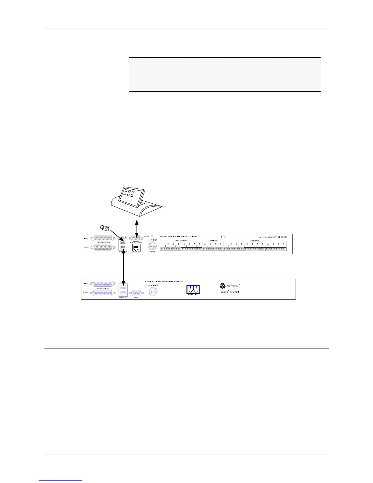
Note. The EF Bus must be connected so that the EF Bus In of one
box is connected to the EF Bus Out of another. Connecting
the EF Bus In to another EF Bus In (or Out to Out) will not
work.
Figure 5. Terminate the EF Bus link on the EF2280 when connecting an EF2201 to one or more EF2280s.
EF Bus Terminator
Cat-5 cable
Vortex EF2280
Vortex EF2201
No terminator is
needed on EF2201