PRE-INSTALLATION
© Polycom, Inc. 5 VORTEX EF2201 Reference Manual
EF2201 F
RONT
AND
R
EAR
P
ANELS
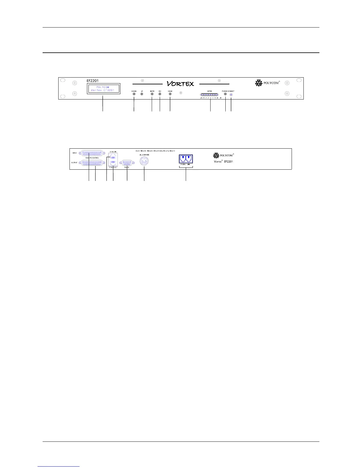
1. LCD DISPLAY. Displays menu instructions for configuration and operation of
the EF2201.
2. D
OWN BUTTON. Scrolls backward through menu items at a particular level or
decreases the value of a parameter.
3. U
P BUTTON. Scrolls forward through menu items at a particular level or increases
the value of a parameter.
4. E
NTER. Enters the menu and allows you to select and change parameter values.
5. E
SC. Returns to the next highest level of menus.
6. H
OME. Returns to the top of the menu structure.
7. L
EVEL INDICATOR. Indicates the level of the selected channel or parameter.
8. P
HONE CONNECT. Takes the phone line on or off hook. If you have an analog
handset connected to the P
HONE jack on the back panel, pushing this button will
disable the P
HONE jack while enabling the LINE jack (see Item 17).
9. P
HONE CONNECT LED. Indicates when the phone line is on or off hook.
10. I
NPUT PARALLEL PORT. Parallel logic input.
11. O
UTPUT PARALLEL PORT. Parallel logic output.
12. EF B
US IN. Connects to EF BUS OUT of another Vortex device.
13. EF B
US OUT. Connects to the EF BUS IN of another Vortex device.
14. RS-232 S
ERIAL PORT. Connect this to an optional RS-232 remote control device,
such as a touch panel or personal computer COM port.
15. P
OWER SUPPLY INPUT. Connects to the external power supply provided with the
EF2201.
16. P
HONE/LINE JACKS. Use the PHONE jack for connecting an analog handset to the
system. Use the L
INE jack for connecting to an analog telephone line.
Figure 2. EF2201 Front and Rear Panels
2 7345 6 8 91
13 14 15
16
11 1210