INTEGRATING THE UNIT INTO YOUR SYSTEM
© Polycom, Inc. 17 VORTEX EF2211/EF2210 Reference Manual
E
CHO
C
ANCELLER
R
EFERENCE
FOR
M
ULTIPLE
V
ORTEX
D
EVICES
In a system with multiple devices, we recommend that one device be designated as
the unit that provides the EF bus reference for the acoustic echo cancellers. This unit
takes its reference signals and places it on the EF bus. All other units that are linked
together may use the EF bus reference as the reference for their echo canceller, or
they can use their own internal reference(s). The reference may include a mix of any
input, with crosspoint gains, including W, X, Y, and Z busses. Set the EF Bus Refer-
ence in the System Menu of the LCD Menu (See “EF Bus Reference” on page 28).
Setting up the
Bus Reference
If all far end audio and program audio sources are on the
same Vortex device.
1. Assign far end audio and program audio sources to Reference 1 on the originat-
ing device.
2. On the EF Bus page in Conference Composer for the originating device, set the
Exported Signals to R
EFERENCE 1. Only one device can put an echo canceller
reference on the EF Bus as the Bus Reference.
3. On all linked devices, set the echo canceller reference to B
US.
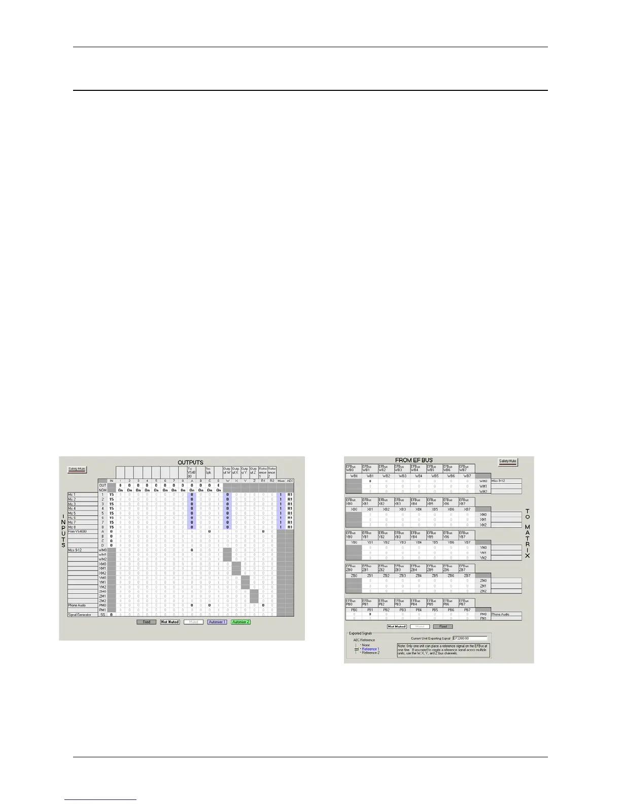
For example, a system uses 1 EF2211, 1 EF2280, and 1 Polycom VS4000 video
codec. The Reference 1 is set up on EF2280 with ID 0. The Matrix for this EF2280
in Conference Composer is shown in Figure 8 and the EF Bus page in Figure 9. Con-
ference Composer will not allow more than one device assign their echo canceller ref-
erence as the Bus Reference. Notice that the phone audio and VS4000 inputs are both
assigned to Reference 1 on the originating EF2280. The Matrix for any linked
devices is shown in Figure 10.
Figure 8. Matrix page of origin EF2280 (ID 00) Figure 9. EF Bus page of origin EF2280 (ID 00)