INSTALLATION
© Polycom, Inc. 7 VORTEX EF2211/EF2210 Reference Manual
Typical EF2211/
EF2210
Connections
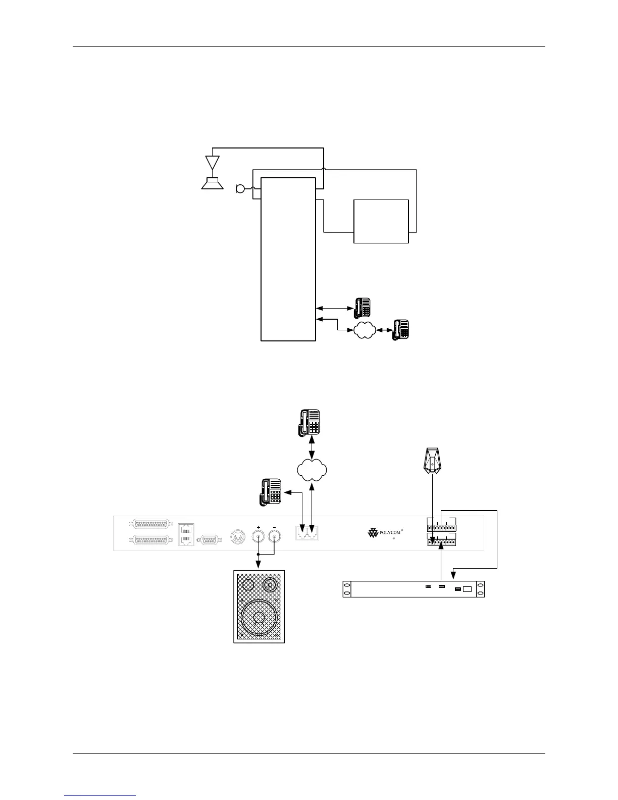
The EF2211/EF2210 will typically be connected to other equipment in a single room
setup as shown below in Figure 3 and Figure 4.
The following steps are typically used to set up the EF2211/EF2210:
• Connect a microphone or line level microphone mix into the M
IC INPUT. Each
Figure 3. Block diagram of typical EF2211/EF2210 connections: a single room using one device.
NOTE: The phone interface is not available on the EF2210.
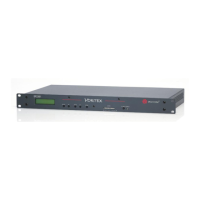
Figure 4. Typical EF2211/EF2210 connections.
NOTE: The phone interface and parallel logic ports are not available on the EF2210
Polycom Video
CODEC
Line In Line Out
PSTN
Line
Vortex
®
EF2211
Mic In
Far In
Prgm In
Amp Out
Far Out
Rec Out
Spk Out
Phone
EFBus OutEFBus In
OUTPUT
INPUT
REMOTE CONTROL
RS-232
EF BUS IN
EF BUS OUT
PHONE LINE
+5, +/-15 VDC+5, +/-15 VDC
RS-232 PIN 2: TXD, PIN 3: RXD, PIN 5: GROUND, PIN 7: CTS, PIN 8: RTS
EF2211
V
ORTEX
SPEAKER
BA1
OUTPUTS
BA1
INPUTS
PSTN
Polycom Video Codec, 4-wire Connection
Vortex
®
EF2211
POLYCOM CODEC
TX RX