WE6 | Data Sheet - Operation Manual 1/24 WK 420 970 | 01.2021
DATA SHEET - OPERATION MANUAL
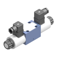
Directional spool valve
electrically operated type WE6
NS 6 | p
max
35 MPa | Q
max
80 dm
3
/min | WK 420 970
APPLICATION
Directional spool valves type WE6… electrically operated
are used to change direction of uid ow in a hydraulic system
which allows to change direction of movement of an actu-
ator (usually a piston rod of a cylinder or a hydraulic motor) and
to control functions: start and stop. These valves are used
for subplate mounting in any position in a hydraulic system.
The product is compliant with the directive 2014/35/UE.
DESCRIPTION OF OPERATION
Main elements of directional spool valve type WE6… : housing 1,
solenoids 3, spool 2, centering springs 4 and manual override 5.
The valve is shifted when spool 2 is moved into one of end positions
by the force of solenoid 3. The return of the spool into neutral
(de-energized) position is caused by the centering springs 4. The shape
of the spool affects connections conguration of ports: A, B, P and T.
Function of ports: P - supply port; T - oil return to the tank; A, B -
ports for an actuator (a cylinder or a hydraulic motor). In case of
emergency, the spool can be shifted manually by the override 5
- only for version with manual override option. Directional spool valve
should be mounted in easily accessible way.
EXAMPLE OF APPLICATION
in a hydraulic system
assembly and operation requirements at www.operating-conditions.ponar.pl
hydraulic uid
cleanliness class
mineral oil
ISO 4406 class 20/18/15
nominal fluid viscosity 37 mm
2
/s at temperature 55°C
viscosity range 2,8 ÷ 380 mm
2
/s
uid temperature range (in the tank) recommended: 40 ÷ 55 °C; max.: -20 ÷ 70 °C
ambient temperature range -20 ÷ 50 °C
maximum operating pressure 35 MPa (ports P, A, B); 21 MPa (port T)
weight
with 1 solenoid
WE6... 1,5 kg
WE6...H... 2,7 kg
with 2 solenoids
WE6... 2,1 kg
WE6...H... 3,3 kg
Flow cross-section
(spool position O)
spool W: 3% of nominal cross-section
supply voltage
of solenoids
DC
12V; 24V; 110 V
AC - plug with rectier
230V-50Hz; 110V-50Hz
AC -di re c t power
supply 230V-50Hz
supply voltage tolerance ± 10%
power consumption (DC) 30 W -
holding power (AC) - 50 VA
switch-on power (AC) - 300 VA
max. switching frequency 15 000/h 12 000/h
switching
time*
ON
5% of pressure change 30 ÷ 60 ms
95% of pressure change 30 ÷ 70 ms
OFF
5% of pressure change 15 ÷ 50 ms
5% of pressure change 30 ÷ 60 ms
protection class IP 65
solenoid coil temperature max. 150 °C
TECHNICAL DATA
* switching time according to ISO 6403 with a directional control valve in horizontal position
CHARAKTERYSTYKI
Charakterystyki oporów przepływu
symbol suwaka
kierunek przepływu
P
→
A
nr wykresu charakterystyki
położenia robocze
schematy wg str. 5, 6
A
,
B
C
D
,
Y
E
F
G
H
J
L
,
W
M
P
U
33
11
31
5
53 3
233 5
7 76
6
2422
-
-
1
1
2
1
1 22
2433
233
5
1
3
1
3
3
1
1
33
położenie centralne
schemat wg str. 5
kierunek przepływu
P
→
A
P
→
B
A
→
T
B
→
T
P
→
T
B
→
A
8
---
G
D1
5
5
Y1
55
--
--
P
→
BA
→
T
B
→
T
0,2
0,4
0,6
0,8
1,0
1,2
0 10 20 30
40 50
60
70
Δ p [MPa]
Q [dm₃ /min]
5
4
2
13
80
8
76
wykresy charakterystyk Δp (Q) rozdzielacza typ WE6...
w wersjach z różnymi suwakami
dla lepkości cieczy hydraulicznej
ν = 41 mm₂ /s i temperatury t = 50 °C
CHARAKTERYSTYKI
UWAGA:
Podane wartości zakresów działania odnoszą się do
symetrycznego przepływu przez wszystkie kanały tzn.
jeżeli z kanału P
do A wpływa olej to taka sama
jego ilość wypływa z kanału B
do T (dot. rozdzielaczy
4-drogowych). Wielkość niesymetrii wpływa na
pogorszenie parametrów.
C
harakterystyki zakresów działania
wykresy charakterystyk p-Q rozdzielacza
typ WE6
... w wersji z elektromagnesami
na prąd stały dla różnych suwaków
10
20
30
35
0
10 20 30 40 50 60 70 80
5
2
1
3
p [MPa]
Q [dm₃ /min]
4
10
10
20
30
35
0
10 20 30 40 50 60 70 80
p [MPa]
Q [dm₃ /min]
9
7
6
8
11
rodzaj suwaka
schematy - str. 5, 6
nr wykresu
charakterystyki
E
,
EA/O
,
EB/O
,
MA/O
,
MB/O
, EA/OF
,
EB/OF
,
MA/OF
,
MB/OF
1
H
,
M
,
L
,
U
,
JA
/O
,
JB/O
,
C/OF
,
D/OF
,
JA/OF
,
JB/OF
,
HA/OF
,
HB/OF
C/O
,
D/O
2
3
F
,
P
A
,
B
4
5
A/O 6
7
8
G
J
9
C
,
D
,
Y
D1
,
Y1
10
GA/O
,
GB/O
,
GA/OF
,
GB/OF
11
10
20
30
35
0
10 20
30
40
50 60
70
80
p [MPa]
1
5
25
15
2
3
4
5
Q [dm₃ /min]
10
20
30
35
0
10
20
30
40
50 60
70
80
p [MPa]
Q [dm₃ /min]
7
5
25
15
6
8
9
wykresy charakterystyk p-Q rozdzielacza typ WE6...
w wersji z elektromagnesami na prąd przemienny
z za
silaniem bezpośrednim dla różnych suwaków
symbol suwaka
schematy - str. 5, 6
nr wykresu
charakterystyki
E, MA/O
,
MB/O
,
MA/OF
,
MB/OF
1
2
3
A
4
5
6
7
8
G
J
L
W
C
,
D
,
H
,
D
/
O
,
HA/O, HB/O, EA/O
,
EB/O
,
JA/O
,
JB/O
, D
/
OF
,
HA/OF
,
HB/OF
,
EA/OF
,
EB/OF
,
JA/OF
,
JB/OF
,
C
/
OF
M
GA/O
,
GB/O
,
GA/OF
,
GB/OF
9
dla lepkości cieczy hydraulicznej
ν
= 41 mm₂ /s i temperatury t = 50 °C
P
A
B
T
T
a
b
12
5
3
4
4WE6 E -32/G24NZ4
6
P
7
WE6.../... HF...
WE6.../...H...
WE6.../...- M
WE6.../...- S
4WE6 E - 32/G24NZ4
SCHEM ATY
PT
A
B
a
a
0
b
b
a
a
0
0
b
b
P
T
A
B
P
T
A
B
położenia
robocze
położenia robocze
i pośrednie
położenia
robocze
położenia robocze
i pośrednie
położenia
robocze
położenia robocze
i pośrednie
WE6.../.
..
WE6...B/...
WE6...A /...
Symbole graficzne rozdzielaczy
3
-położeniowych
Symbole graficzne suwaków
S
ymbole graficzne rozdzielaczy 2-położeniowych
wersje z położeniami a, 0
wersje z położeniami 0, b
PT
A
B
a
ba
a
0
0
b
b
P
T
A
B
P
T
A
B
WE6.../.
..H...
WE6...B
/...H...
WE6...A /.
..H...
A
B
P
T
a
b
0
a
b
A
B
P
T
a
0
A
B
P
T
b
0
A
P
T
B
A
B
P
T
b
0
WE6.../... - S...
WE6...B/... - S...
WE6...A /.
.. - S...
WE6...B
/... - M
WE6...A /.
.. - M
P
T
a
0
b
a
0
0
b
E
F
G
H
J
L
M
P
U
EA
FA
G
A
HA
J
A
LA
MA
P
A
U
A
EB
FB
GB
HB
JB
LB
MB
PB
UB
P
T
A
B
P
T
A
B
A
B
P
T
A
B
a
0
b
a
0
P
T
A
B
0
b
P
T
A
B
W**
WA**
WB
*
P
T
A
B
a
a
0
b
b
a
0
0
b
P
T
A
B
P
T
A
B
WE6.../.
..HF...
WE6...B
/...HF...
WE6...A /.
..HF...
a
a
0
0
b
b
P
T
A
B
P
T
A
B
a
a
0
0
b
b
P
T
A
B
P
T
A
B
b
a
b
a
b
WE6...B
/O...*
WE6...A /O
...*
WE6...B
/OF...*
WE6...A /O
F...*
a
a
0
b
a
0
G
G
UWAGI:
(*) - wersje dostępne z tylko suwakami - schematy: EA, GA, HA, JA, MA, EB, GB, HB, JB, MB
(**) - przekrój przepływu w położeniu środkowym realizowany przez suwak W - 3 % przekroju nominalnego
SCHEM ATY
a
a
a
a
b
b
b
b
a
b
b
P
T
A
B
P
T
A
B
P
T
A
B
P
T
A
B
położenia
robocze
położenia robocze
i pośrednie
położenia
robocze
położenia robocze
i pośrednie
WE6.../O...*
WE6.../O
F...*
WE6.../.
..
WE6.../...
Symbole graficzne rozdzielaczy
2-położeniowych
Symbole graficzne suwaków
wersje z położeniami a, b
a
a
a
a
a
a
b
b
b
b
b
P
T
A
B
P
T
A
B
A
B
WE6.../O...H...*
WE6.../O
F...H...*
WE6.../.
..H...
PT
a
b
b
P
T
A
B
WE6.../...H...
B
P
T
a
b
A
P
T
a
b
B
A
WE6.../.
.. - S...
WE6.../.
.. - M
A
B
P
T
b
a
A
B
P
T
b
a
WE6.../... - S...
WE6.../.
.. - M
UWAGA:
(*) - wersje dostępne tylko z suwakami - schematy: A, C, D
a
b
a
b
P
T
A
B
P
T
A
B
A
C
D
B
Y
a
b
P
T
A
B
a
b
P
T
A
B
a
b
a
b
P
T
A
B
P
T
A
B
a
b
P
T
A
B
a
b
P
T
A
B
D1
Y1
a
b
a
G
G
A
B
M
P
T
4WE6 J...
PRZYKŁAD ZASTOSOWANIA W UKŁADZIE
HYDRAULICZNYM