Version 2.1
Update: April 2016
PONSEL Mesure – Aqualabo Contrôle
35 Rue Michel Marion – 56850 CAUDAN, FRANCE
Tel.: +33(0)2 97 89 25 30 – Fax: +33(0)2 97 76 55 72
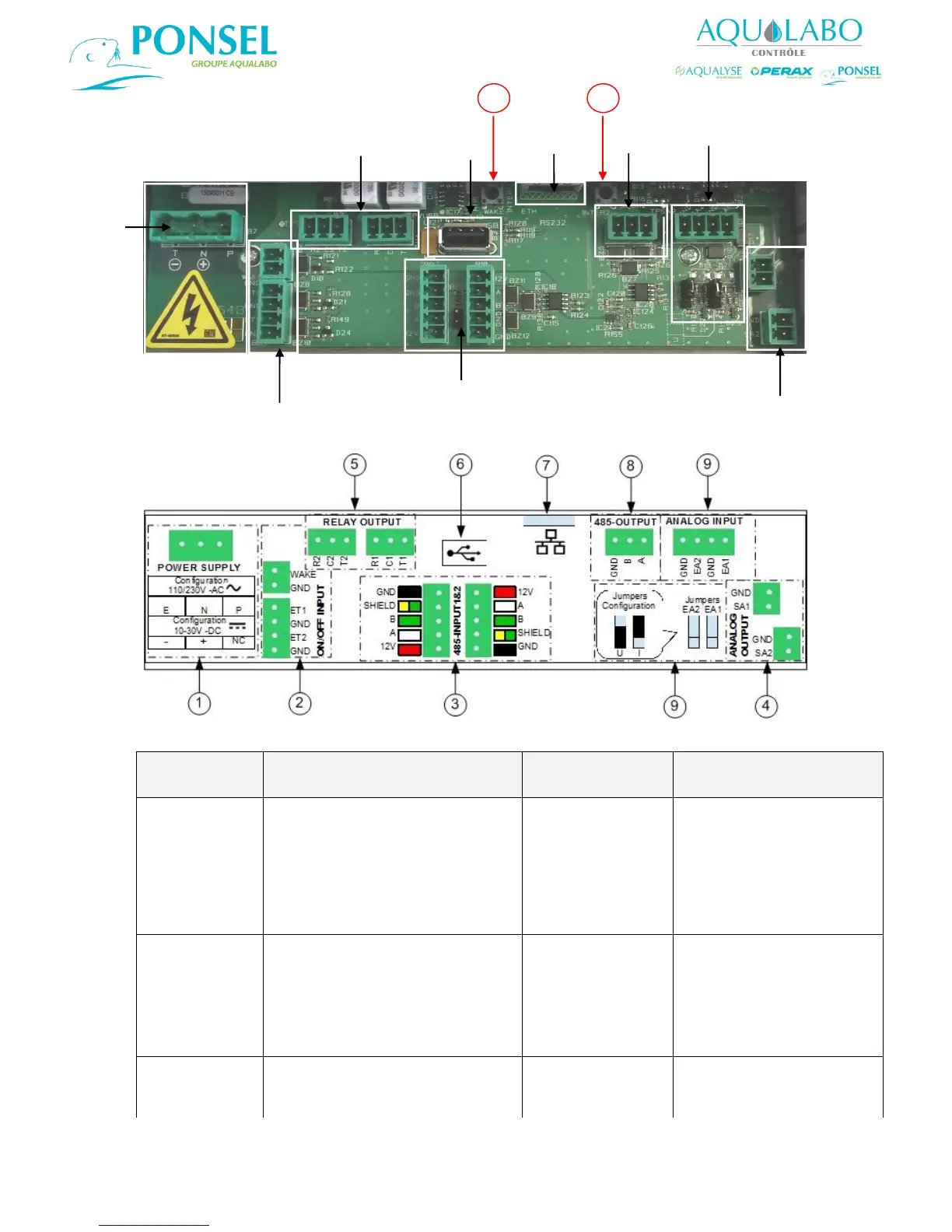
3.2.2 Description of the wiring.
Diagram 3: Photograph showing the terminals on the circuit card
Diagram 4: Diagram of the terminals affixed (as a self-adhesive label) to the protective cover
Terminal
identification on
circuit card
Terminal identification on
protective cover (self-adhesive
label)
110-230 V a.c. power supply
Yellow and green - Earth
Blue - Neutral
Brown - Phase
10-30 V d.c. power supply
Black
Red
T (-)
N (+)
P
T (-)
N (+)
P
WAKE – Inactive
GND – Inactive
ET1
GND
ET2
GND
WAKE – Inactive
GND – Inactive
ET1
GND
ET2
GND
3 – Digital
sensors
RS485 - INPUT
Two digital sensor inputs
V- sensor power supply: Black
Shielding – Yellow and Green
RS485 - Green