Version 2.1
Update: April 2016
PONSEL Mesure – Aqualabo Contrôle
35 Rue Michel Marion – 56850 CAUDAN, FRANCE
Tel.: +33(0)2 97 89 25 30 – Fax: +33(0)2 97 76 55 72
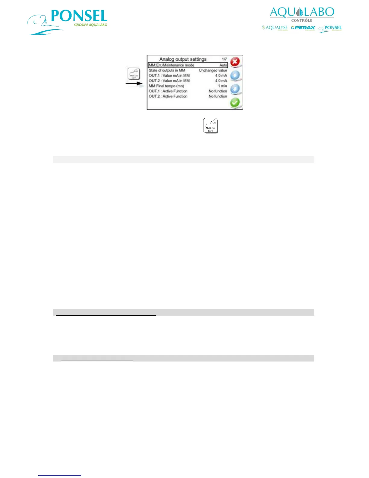
6.2.5 Configuring the Analog outputs.
To access the "Analog output settings" window, select the icon in the Main menu.
The functionality offered for the setting up of the two analog outputs is described in the table below:
Used to set the Maintenance Mode to one of the following modes:
Automatic (the default option, and which is activated when the calibration
menu is used, or if there is a loss of communication, etc.)
Inactive
Manual (this mode is activated manually when maintenance or other work is
performed on the device).
In Maintenance Mode, the analog outputs may return a value corresponding
to:
- the last value measured,
- a fixed (unchanged) value which shall be defined in the "OUT. 1: Value mA
in MM" and "OUT. 2: Value mA in MM" lines.
This line is used to set the value which will be returned by analog output 1
when the device is in Maintenance Mode (between 0 and 21 mA).
This line is used to set the value which will be returned by analog output 2
when the device is in Maintenance Mode (between 0 and 21 mA).
Used to set a time delay which shall begin when the Maintenance is
completed, to allow a period of time for the measurement to stabilize. The
possible values are: 0 to 60 minutes (1 min is the default setting).
Configuration of the Analog Output 1
Configuration of the output 1 according to 4 choices:
No function
Recorder
Test – Fixed Value
PID Controler
If Active Function : Recorder
This function activates analog output 1.
Used to set output 1 to Data logger mode (for when the output is connected
to a controller/data logger).
Used to set output 1 to operate within a range of 0-20 mA or 4-20 mA.
OUT. 1: Parameter
linked to DL
Used to select the parameter whose value shall be outputted via analog
output 1:
Sensor 1: Primary parameter
Sensor 1: Secondary parameter
Sensor 2: Primary parameter