EasyManua.ls Logo

Ponsel ACTEON 5000 - Digital Sensor Connections

Ponsel ACTEON 5000
56 pages
Print Icon
To Next Page IconTo Next Page
To Previous Page IconTo Previous Page
Loading...
19
Version 2.1
Update: April 2016
PONSEL Mesure Aqualabo Contrôle
35 Rue Michel Marion 56850 CAUDAN, FRANCE
Tel.: +33(0)2 97 89 25 30 Fax: +33(0)2 97 76 55 72
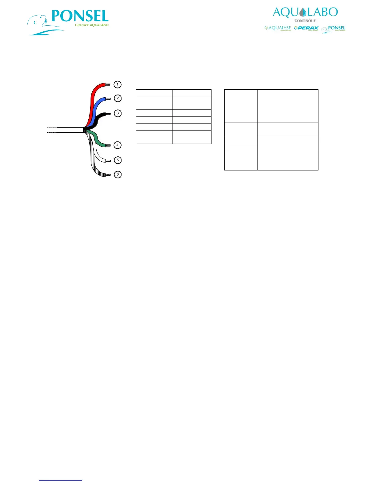
Electrical connections for digital sensors:
Diagram 5 below shows the electrical connections required for digital sensors when the cable lengths
are 15 meters or less, and when the cable lengths are more than 15 meters. When a CTZN sensor is
connected, the wiring diagram to be used is that corresponding to a cable length of more than
15 meters, regardless of the length of the cable.
Diagram 5: Sensor connection for a cable length of 15 meters or less, and of more than 15 meters.

1 - red
V+ power
2 - blue
SDI-12 Not
connected
3 - black
GND
4 - green
B " RS-485 "
5 - white
A " RS-485 "
6 -
green/yellow
Cable shield
Connect cable 3 and 6
RED
YELLOW
ORANGE
VIOLET
PINK
V+ power
2- blue
SDI-12 Not
connected
3 - black
V- power
4 - green
B " RS-485 "
5 - white
A " RS-485 "
6 green/
yellow
Cable shield
Cable length more than 15 meters
Connect cable 3 and 6

Table of Contents