17
5. Loosen the side hex socket screw (4).
Move the guide block support bracket (6)
in or out until the blocks are just behind
the saw teeth. Tighten the screw. (Fig. R)
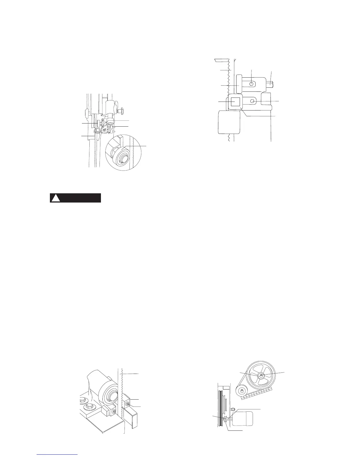
Support bearing
6. Loosen the bearing hex socket screw (7)
with the hex wrench.
7. Move the blade support bearing shaft (8)
in or out until the support bearing (9) is
1/64 in. (0.4 mm) behind the saw blade.
8. Tighten the bearing hex socket screw.
9. The back edge of the blade (3) should be
positioned 1/16 in. (1.6 mm) to 1/8 in.
(3.2 mm) from the right edge of the
support bearing (9), as shown.
PULLEY ALIGNMENT (FIG. S)
The pulley alignment has been adjusted
at the factory and shouldn’t require further
adjustment. If adjustments are required
or belt needs replacing, please follow
these procedures:
1. Place a straight edge in the front groove
of both pulleys, behind the blade wheel.
2. Turn the hex socket screw (1) in the
side of the motor pulley (2) to loosen the
pulley on the shaft.
3. Adjust the motor pulley in or out on the
motor shaft (3) to align the edges of the
two pulleys.
4. When aligned, tighten the hex socket
screw on the side of the motor pulley.
NOTE: This blade support bearing prevents
the blade from moving back too far and
damaging the saw teeth setting.
12. Check the lateral position of the support
bearing (8). The vertical back edge of the
blade (3) should overlap the front face of
the support bearing 1/16 in. (1.6 mm) to
1/8 in. (3.2 mm) to the left of the right
bearing edge, as shown.
LOWER BLADE GUIDES AND SUPPORT
BEARING (FIG. Q, R)
To avoid injury, turn the switch OFF and
disconnect the saw from the power source
before making any adjustments. NEVER
make adjustments with the machine running.
NOTE: Make sure the blade is tensioned and
tracking properly. The lower blade guides and
support bearings should always be adjusted
after the blade is tensioned, the tracking is
adjusted, and the upper blade guides and
upper support bearings are properly adjusted.
Blade guides
1. Loosen both front hex socket screws (1)
with a hex wrench.
2. Move the guide blocks (2) as close to the
sides of the blade (3) as possible without
pinching it.
3. Using the feeler gauge, measure the
spaces between the guide blocks and the
blade. Adjust to 0.002 in. (0.05 mm).
4. Tighten the hex socket screws. (Fig. Q)
Fig. P
8
6
7
8
3
WARNING
!
1
2
3
Fig. Q
Fig. R
3
9
2
7
8
4
6
Fig. S
1
3
2
3
2