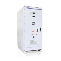
VS65 SERIES MV SOFT STARTER
G7.6 /
Analogue
Output low set
point
It scales de Analogue Output in order to get a better reading
G7.7 /
Analogue
Output high set
point
4.8. Group 8 – G8: DUAL SETTING
Enable/Disable a second adjustment for [G4] acceleration, [G5] deceleration and for the
overload curve [G3.3].
When a second parameter is required set select Dual Setting to Yes. This second adjustment is
activated by one of digital inputs.
Applications: Mills, crushers and any application that at a certain operation stage requires a
harder/softer parameter set.
G8.2 / Dual
setting Torque
Pulse
Choose the torque pulse level applied to the motor for the time specified at [G8.3]
Set this value in conjunction with G8.3 to initiate a first acceleration of the motor.
G8.3 / Dual
setting Pulse
Time.
Sets the time for the torque pulse [G8.2] to be applied.
G8.4 / Dual
setting Initial
Torque
Establish the initial torque to be applied to the motor at the beginning of the ramp up.
When adjusting, refer to parameter [G4.4] for further information.
G8.5 / Dual
setting Initial
Torque Time
Set the time for the initial torque [G8.4] to be applied to the motor.
Proceeding with the adjustment, refer to parameter [G4.5] for further information.
G8.6 / Dual
setting
Acceleration
time
Adjust the motor acceleration time from standstill to nominal speed, provided that no current limit
occurs as that will cause a longer acceleration time.
The time setting depends on the application. Refer to parameter [G4.6] for further information.
G8.7 / Dual
Setting current
limit
Maximum current a motor can draw during the acceleration/deceleration.
Set to determine the maximum allowed current consumption during the acceleration /
deceleration. Refer to parameter [G4.7] for further information.
G8.8 / Dual
setting
Freewheel stop
Set the required stop mode. The stop could be controlled through a ramp down voltage or
uncontrolled where the time to stop depends on the inertia of the load, the freewheel stop.
Set N" for a spinning stop, set Y, in case a controlled stop is required. Refer to parameter [G5.1]
for further information.
Value that depends on the soft starter rated current
DT0034B
13,6mA
%
20mA
12mA
60% 200%100%0%
mA
Format 0-20mA
Lower limit 0%
Higher limit 100%/ 200%
Format 4-20mA
Lower limit 0%
Higher limit 100%/ 200%
%
20mA
8,7mA
4mA
60% 100% 200%0%
mA

 Loading...