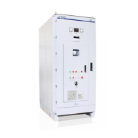
VS65 SERIES MV SOFT STARTER
G8.9 / Dual
setting
deceleration
time
Establish the required time for a controlled stop.
For this parameter adjustment, begin with a short time and increase it until desired stop is
achieved. Refer to parameter [G5.2] for further information.
G8.10 / Dual
setting
deceleration
mode selection
In applications where it’s desired to avoid water hammer effect, select this algorithm. In other
applications, the normal deceleration ramp is sufficient.
When setting for applications with water hammer problems during deceleration, select the
hammer algorithm. In other applications set normal deceleration algorithm.
When selecting the hammer algorithm for the deceleration, 2 parameters must be set to properly
adjust the stop.
Percentage of time the hammer algorithm is active during the deceleration time. Minimum torque
the motor must deliver during the stop.
To correctly adjust the deceleration of such an application with hammer problems you may need
to perform an interactive process by trial and error until the application is correctly
commissioned.
G8.11 / Dual
setting hammer
factor
Set the percentage of time for the hammer algorithm is to be active during deceleration.
It is set in % of the deceleration time of the motor [G8.9].
G8.12 / Dual
setting
minimum
torque
Set the minimum torque to be applied during deceleration (for Hammer Algorithm).
G8.13 / Dual
setting in phase
sequence at
the input of the
soft starter
This parameter sets the correct phase sequence at the input, when starting the motor. It can
happen that the soft starter tries to start with a phase sequence at the input different than the
one we have set. In this case the soft starter trips on F2 WRONG PH/SQ.
Before adjusting, determine your input phase sequence. Then set this parameter according to
this sequence.
Note: When operating at SLOW SPEED or DC BRAKE you must always select a phase
sequence (L1 L2 L3 or Inverse Sequence). The option
[1 NO SEQ PROTECT] is not allowed for these modes.
G8.14 / Dual
setting overload
motor current
Determines the current value in which the equipments overload protections will activate. For
more details consult the parameter [3.2]
In order to proceed with the adjustment, check the nameplate current and introduce the value on
screen.
G8.15 / Dual
setting of
overload curve
This parameter sets the overload motor current protection at nominal conditions. For more
details, please consult parameter [G3.3].
Set [15 OV/LOAD T =1] in case you need a fast response under overload conditions. However, if
you need a slow response, then select [OV/LOAD T =10]. For normal operation adjust to its
default setting [OV/LOAD T =5].
G8.16 / Dual
setting starting
Overload
Factor
This parameter adjusts the overload curve during acceleration. Use this parameter when trying
to accelerate high inertia load. In case of pumps, fans (Torque = K x Speed²) leave as default
(100%).
This parameter is only active during acceleration and not in normal running conditions, where
only [G3.2] and [G3.3] are active.
For low inertia pumps, fans (Torque = K x Speed²) leave as default value (100%).
For mills, crushes and centrifuges (high inertia moment) start with low starting overload factor
(150%) and increase this value till we can accelerate this load without tripping on F4
OVERLOAD.
G8.17 / Dual
setting PTC
motor option
Enables /Disables the Motor PTC option in dual setting.
Motor warming detection through a PTC thermistor. For further information consult [G3.5]
parameter.
G8.18 / Dual
setting of under
load current
Under load current determines the current level the motor must not operate below.
Usually adjust to 50% of the nominal current of the motor.
Application: This protection detects mechanical problems, such as broken shafts, belts. When
this occurs, the motor will run under no load conditions.
When working with pumps, this protection help to detect no load pump operation, due to a lack
of water or pump input pipe water position.
G8.19 / Dual
setting of under
load delay
This parameter sets the maximum allowable operation time under load conditions before
tripping.
Set depending on the application, but should be set to trip as soon as a condition occurs.
Applications: Pumps, fans.
Value that depends on the soft starter rated current

 Loading...