POWER ELECTRONICS
VS65 SERIES MV SOFT STARTER
WIRING ACCESS AND CONNECTION
31
6.4. Wiring recommendations
CAUTION
The installation must be done by qualified personal.
Otherwise, the equipment can be damaged and lead to injury to people.
The VS65 series soft starters are built-in an earth busbar. First of all, connect the input and output
shields, and the motor earth to the earth busbar of the soft starter (PE).
Connect the three input phases to the L1, L2 y L3 input terminals. Connect the three motor phases to the
U, V and W output terminals. These terminals are located on the back part of the soft starter, as it has
been described on the previous section.
The copper bars or the cables must satisfy the intensity capacity rule and the isolation voltage.
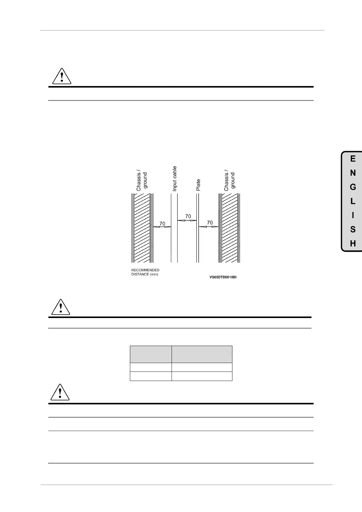
The cables installation must respect the minimum safety clearance between the plates and the
equipment as shown in the following figure.
Figure 6.10 Input cables safety distance
CAUTION
In any case the distance between plates and equipment should never be smaller than 60mm
Torque specifications for MV power connections in VS65 soft starter:
Bolt size
Torque at full
engagement (Nm)
M10 40
M12 60
CAUTION
ge (input supply) must never be connected to U, V and W terminals. Otherwise, the drive
will be damaged.
It is absolutely necessary that the installer guaranties the correct observance of the law and the
regulations that are in force in those countries or areas where this device is going to be installed.
For safety reasons it is determinant to
the grounding resistance of the plant itself.
This
must be established before the first start up of the plant and with the drive disconnected.
It is responsibility of the installer, to provide the adequate number, type and cross section
grounding conductor alongside with the characteristics of the drive used and of the Plant in order to
minimize the grounding resistance, that compliance with the local and national regulation.

 Loading...