EasyManuals Logo

Power Electronics VS65 Series Hardware And Installation Manual

Power Electronics VS65 Series
51 pages
To Next Page IconTo Next Page
To Previous Page IconTo Previous Page
Page #36 background imageLoading...
Page #36 background image
VS65 SERIES MV SOFT STAR
TER
POWER ELECTRONICS
34
INTERFACE
7. INTERFACE
VS65 integrates multiple pushbuttons, indicators and pilots, suitable for adverse industrial environment.
The interfaces are located on the top and lower front doors.
7.1. Upper door pilots and indicators
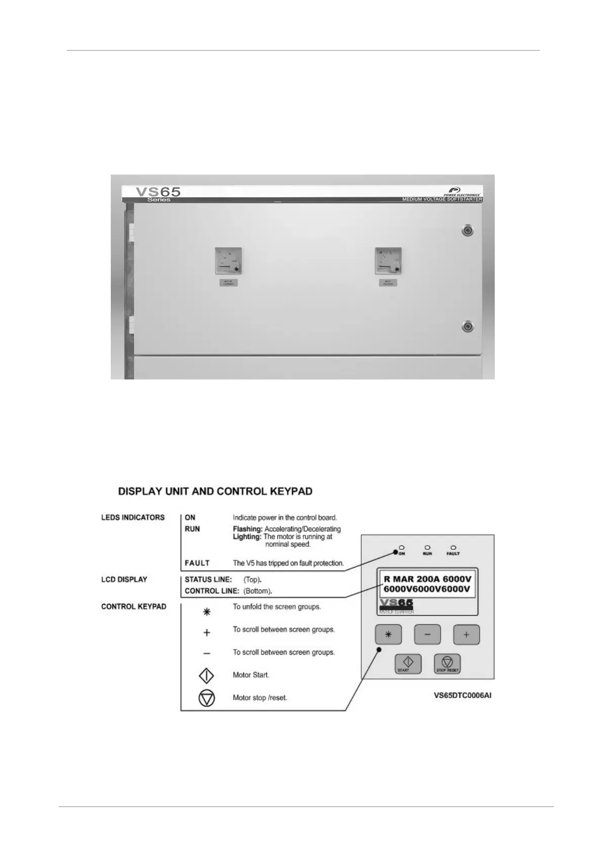
Figure 7.1 Top door indicators
Ammemeter [MOTOR CURRENT]: It shows the motor current. The relationship between Real
current / Measured current is 750 / 5A.
Voltmeter [INPUT VOLTAGE]: It shows the equipment input voltage. The relationship between
Real voltage / Measured voltage is 6600 / 110V.
7.2. Alphanumeric Display
Figure 7.2 Display Unit
For further information consult Software and Programming Manual.

Other manuals for Power Electronics VS65 Series

Questions and Answers:

Question and Answer IconNeed help?

Do you have a question about the Power Electronics VS65 Series and is the answer not in the manual?

Power Electronics VS65 Series Specifications

General IconGeneral
BrandPower Electronics
ModelVS65 Series
CategoryController
LanguageEnglish

Related product manuals