POWER ELECTRONICS
32
WIRING ACCESS AND CONNECTION
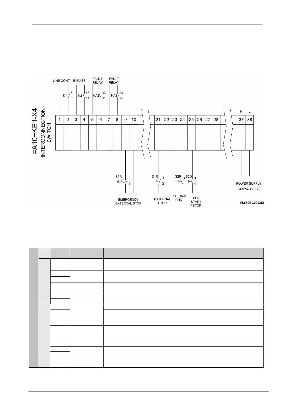
6.5. Control Terminals
The user interconnection switch (X4) is located in the frontal upper part of the locker, where the available
control signs are found in accordance with the diagram attached.
For other configuration, contact Power Electronics.
Figure 6.11 Interconnection control boards diagram
On the control voltage terminal block, control wiring is secured in place by 3mm spring terminals. Use a
screwdriver whose dimensions are 0.6x3.5mm to open the terminal clamp, and then insert the wire into
the terminal cage. Release the clamp by removing the screwdriver. The maximum allowed control cable
section is 2.5mm²and the torque must be between 0.4Nm and 0.8Nm.
X4
TERM. SIGNAL DESCRIPTION
OUTPUT RELAYS
1
K1
Auxiliary contact of the line contactor (NC). It shows the line contactor’s status (opened or
closed). Potential free. (Max 200mA)
2
3
K2
Auxiliary contact of the bypass contactor (NO). It shows the bypass contactor’s status
(opened or closed). Potential free. (Max 200mA)
4
KA2
(NO) and (NC) Output relay shows if the soft starter is in a failure status. Potential free. (Rated:
6A@250VAC - 6A@28VDC) (Max 200mA).
KA2
DIGITAL INPUTS
EMERGENCY
STOP
Door mounted emergency st
op pushbutton contact (NC) (Factory Wired do not use)
External emergency stop pushbutton contact (NC)
STOP
Door mounted stop pushbutton contact (NC) (
Factory Wired do not use)
External STOP push button.
23
START
. Enabled when VS65 door mounted mode selector
is in local control mode (Factory wired do not use).
24
pushbutton. Enabled when VS65 door mounted mode selector is in
remote control mode.
PLC START/
STOP
PLC Start/Stop Connection (NO). It allows the connection of a Start/Stop digital signal. Enabled
when VS65 door mounted mode selector is in remote control mode.
CPS
Input terminals for control board power supply (230Vac / ± 10%). Other voltage ratings are
available on demand. Max Power consumption (Max 1A@24Vdc).
Note:
CPS: Control Power Supply, UPS: User Power Supply

 Loading...