POWER ELECTRONICS
44
PREVENTIVE MAINTENANCE
9. PREVENTIVE MAINTENANCE
The VS65 series Medium Voltage soft starter is highly reliable and has easy maintenance. Therefore, to
ensure a long working life it is recommended to take into account the following instructions:
CAUTION
Make sure the soft starter
is completely disconnected from the power supply and earth grounded
before any maintenance operation is carried out.
In order to prevent electric risks, disconnect the power supply input, earth ground the equipment and
remove the control voltages before working in the equipment. Warning and safety labels should be
properly placed in terminals, covers and control panels in accordance with local codes. Otherwise, electric
shock hazard exists.
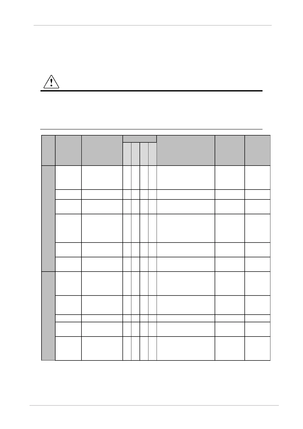
Inspection site
Inspection
element
Inspection
Period
Inspection method Criterion
Instrument of
measurement
Daily
1 year
2 years
3 years
All
Ambient
conditions
Are there dust particles?
Are the ambient tempe-
rature and the humidity
within specification?
o See “Warnings”
-10ºC to +40ºC
Humidity: below
90% non-
condensing.
Thermometer,
Hygrometer,
recorder.
Module
noises or oscillations?
o Visual and audible.
anomalies.
Input power
Is the input power to the
main circuit correct?
o
Measure the voltage between
terminals L1, L2, L3 and N.
multimeter.
Tester.
Power
connections
Are they properly
tightened the power
connections?
o
Measure the temperature and
torque about the power
connections.
temperature is
homogeneous
between cables
and lower than
70ºC.
thermometer
or thermo
graphic
camera.
Torque key.
Control input
power
Is the input power to the
control circuit correct?
o
Measure the voltage between
terminals L and N.
multimeter.
Tester.
Trigger board
power supply
Is the input power to the
control circuit correct?
o
Measure the voltage between
output terminals.
multimeter.
Tester.
Main circuit
All
Components are very
hot?
The transformer
insulation is correct?
o
Visual check.
Measure the transformer resistor.
No anomalies.
The measure
must be higher
than 100MΩ.
Ohmmeter.
Conductor/
Cable
corroded?
Is the sheathing of the
cable damaged?
o
o
Visual check. No anomalies.
Terminal Is any damage visible? o Visual check. No anomalies.
Relay
corroded?
Switches correctly?
o Visual and audible. No anomalies
Contactor
Is there any contactor
chatter?
Is the contact damaged?
o
o
Visual and audible.
Measure the torque about its
connections.
No anomaly.

 Loading...