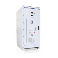
POWER ELECTRONICS
VS65 SERIES MV SOFT STARTER
CONFIGURATION, LOW VOLTAGE TRIAL AND COMMISSIONING
37
8. CONFIGURATION, LOW VOLTAGE TRIAL
AND COMMISSIONING
8.1. Before Commissioning Observations
• Check no foreign matter is found inside the equipment.
• Verify the auxiliary power supply is 230VAC ±10%.
• Verify the interconnection signs are correct and in accordance with the manual.
• Check the soft starter power supply is connected to the L1, L2, L3 terminals and the motor power
supply to U, V, W terminals. Confirm that the triphasic voltage at soft starters input is within the
specifications and the motor characteristics plate is in accordance with the equipment installed.
Note: The VS65 are factory configured to: START, STOP, and RESET from keyboard.
• The digital input state can be checked on the screen EDG X 0 0 0 0 F
X indicates the input is active, 0 means the digital input has not been activated for the
moment.
K indicates that the motor PTC is not active and F that the PTC input is active.
• Firstly, control through the digital inputs is disabled by the screen [G6.1 CONTROL MODE=1
LOCAL]. This means the soft starters run and stop is carried out by display and any modification of
the digital inputs will have no major consequence than the screen visualization EDG= 0000K.
• Default relay configuration:
Relay 1: Line. Connected during the acceleration ramp and during the deceleration ramp.
Relay 2: Bypass. Connected at the end of the acceleration ramp and disconnected at the beginning of
the deceleration ramp.
Relay 3: Fault (Active in case of fault).
 Loading...


