MICRO Installation & Owner’s Guide 2018 | www.power-pole.com | 9
2. Use the (1) heat shrink butt connector
D
to connect the red wire to the red fuse holder wire and crimp.
MICRO Driver Unit
The MICRO Driver comes programed as a single unit. For
proper performance do not program a single unit as port or
starboard. If you have a single unit proceed to the Owners
Guide for calibration instructions prior to using the unit.
Programming Dual MICRO Driver Units
1. With both MICRO Driver Unit locations identified,
begin with the starboard side unit. Press and hold the
“Program” button for 6 seconds until the LED turns red.
2. Press the UP button to set as the starboard side unit.
The LED will flash red one time indicating that the
programming has been completed successfully. Press
and release the program button to save and exit. The LED will flash red one time.
3. On the port side, repeat Step 1 to enter programming mode. Press the DOWN button to set as the
port side unit. The LED will flash red twice indicating that the programming has been completed
successfully. Press and release the program button to save and exit. The LED will flash red twice.
Programming Dual MICRO Driver Units to a Single Wireless Controller
When installing dual units, you can program a single Dash Switch and/or Key-Fob remote to control
both driver units by following the steps below.
1. Determine which unit is paired with the controller by pressing the UP or DOWN button.
2. Press and hold the Program/Pair button on the other unit for three seconds until the LED turns green.
3. Press and hold the UP or DOWN button on the controller until both units respond.
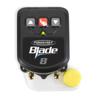
Installing the Dash Switch
NOTE: You should make sure your Dash Switch is paired with your
single or multiple driver units before installation.
Mark and drill a hole with 7/64” drill bit to fasten switch using the
(2) screws
F
supplied (do not over tighten). Or you may choose to use
adhesive strip
P
also supplied.
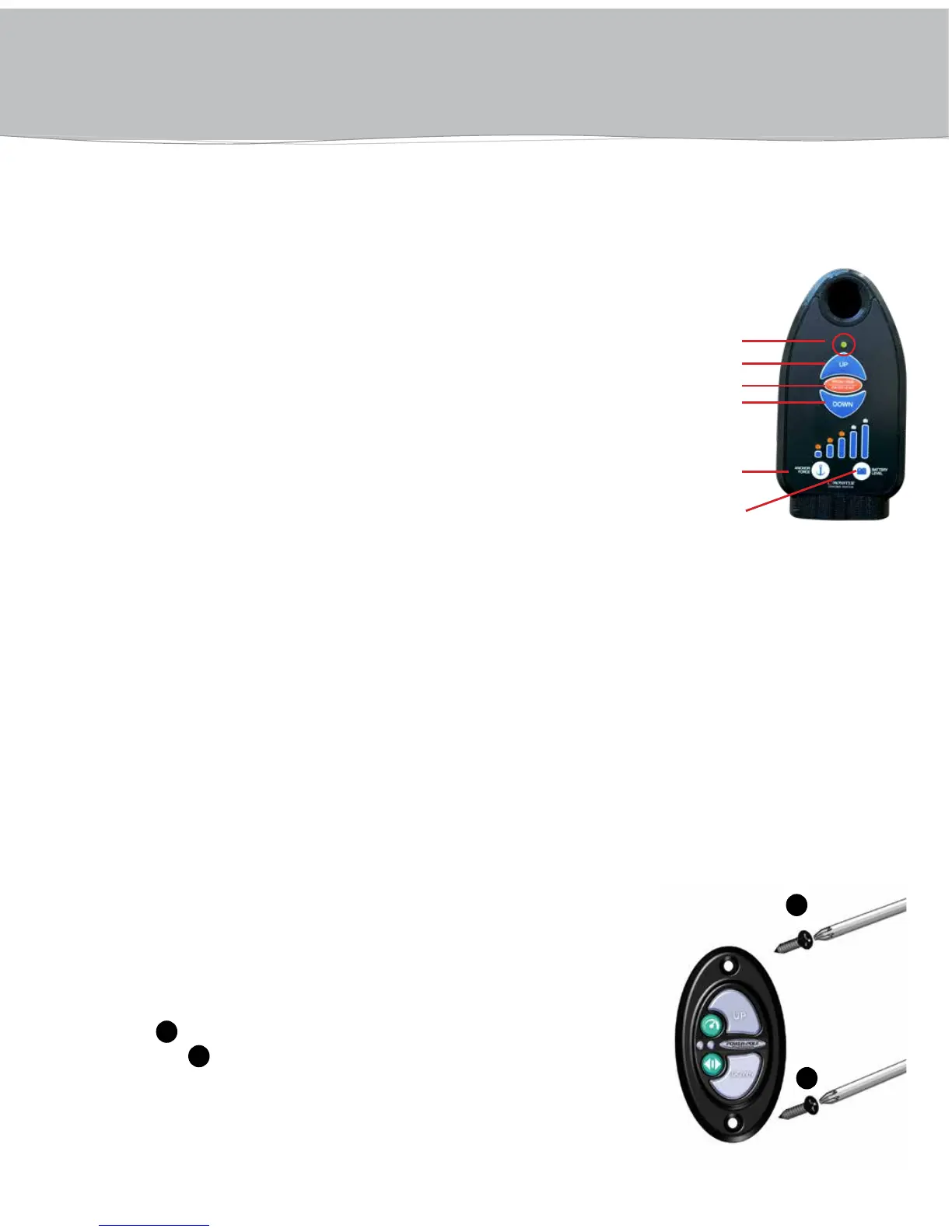
PROGRAMMING The MICRO
LED Programming Light
UP
Program/Pair
DOWN
Anchor Force
Battery Level
F
F