8 | MICRO Installation & Owner’s Guide 2018 | www.power-pole.com
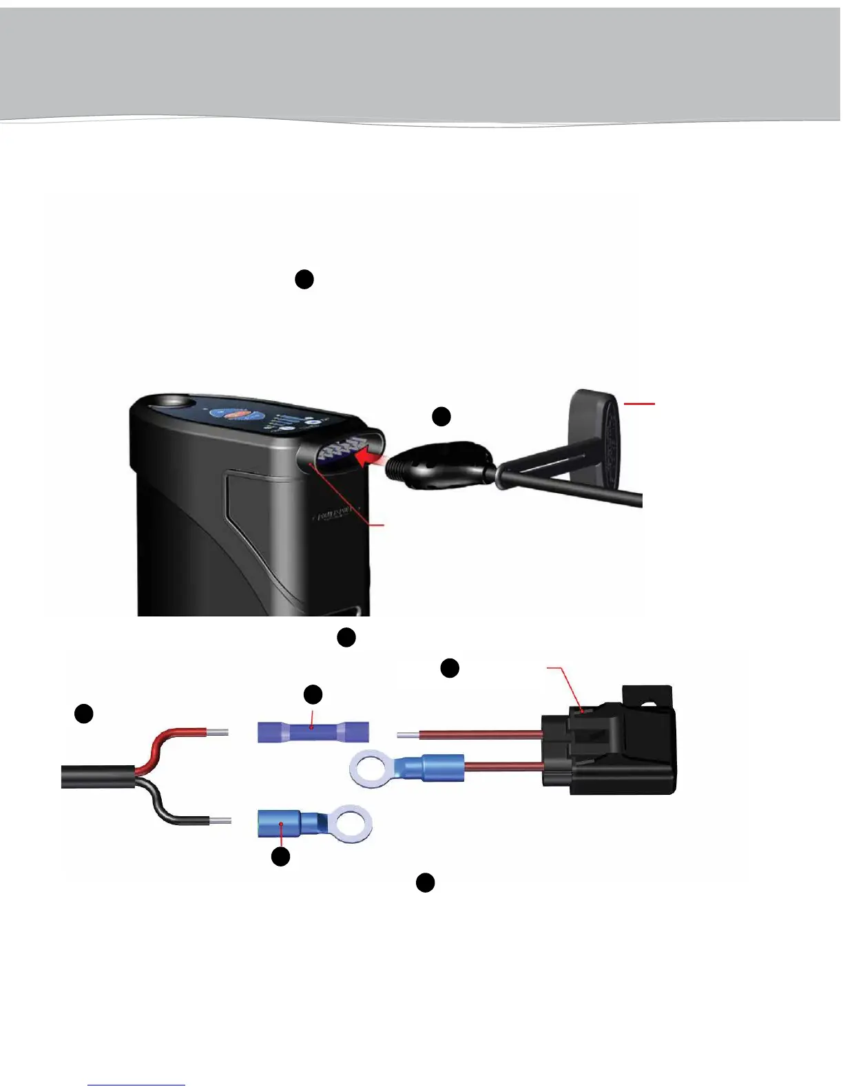
1. Plug the male plug connector
H
into the MICRO Driver Unit and route wires through the boat
to power source.
IMPORTANT: Power cord must be disconnected
when the anchor is not in use or
while charging 12 volt DC battery.
MICRO Driver Unit
Female plug connection
– Fuse Holder
– Power Cord End
Connecting the MICRO Driver Unit to Power Source
Using a 12 volt DC battery
2. Use the (1) heat shrink butt connector
D
to connect the red wire to the red fuse holder wire and crimp.
ATTACHING POWER Source
3. Use the (1) heat shrink ring terminal connector
E
to connect to the black wire and crimp.
4. Connect the red fuse holder ring terminal to the main battery cut-off switch and
the black ring terminal to the negative post on the cranking battery. The LED light
on the top of the MICRO Driver Unit will begin flashing green.
NOTE: If 12 volt battery is not available, the Micro Driver Unit can also be powered by the Micro
Battery Pak, sold seperately.
NOTE: Dust cover
must be in
place while
power cord is
disconnected.
H
H
D
E
I