NCNC
NONO
COMCOM
Alarm Control
Panel Trigger
Contact Opens
When Bell Circuit
Is Active
Typical Alarm Interface Relay
(Supplied by others)
+
_
Relay 4 configured
for alarm activation
White
White
Gnd
Gnd
Yellow
Yellow
NO
NO
NO
1
2
3 4
5
6 7
Motor Connection
24V
24V
+
Brake
Resistor
Load
Resistor
+ Battery
- Connection
+ PSU
- Connection
+ 24V Aux
- 0V Output
L
L
Green
Green
NC
NC
NC
0V
0V
-
H
H
Brown
Brown
COM
COM
COM
Open
Emer. Retract
Com
Close
Com
Fire
Access
Alarm
Input 1
Alarm
Input 2
Alarm
Test
Stop
Open
Emer. Retract
Com
Close
Com
Fire
Access
Alarm
Input 2
Alarm
Input 1
Test
SC
Battery Fuse 7.5A
Automotive Blade
Aux Fuse 2A
OSE
Receiver
OSE
Transmitter
SELECT
Prg UP
Prg DOWN
14
13
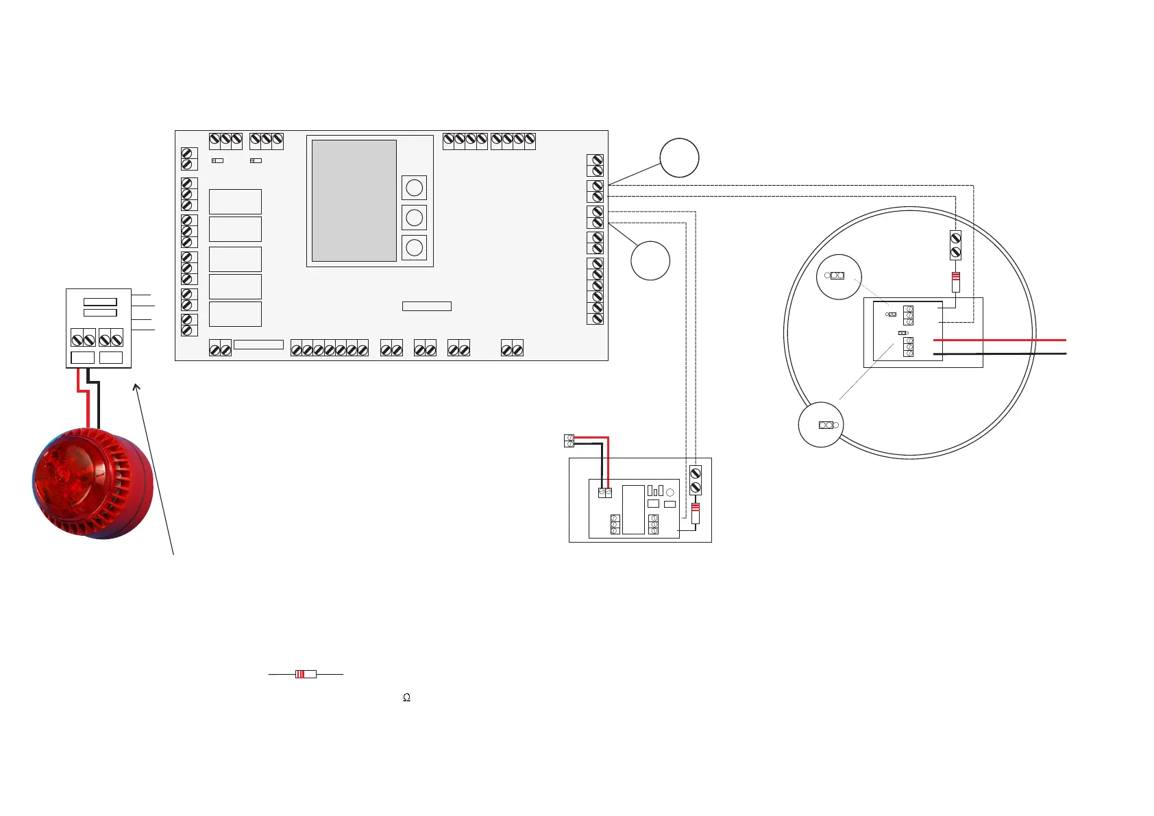
P1000 Alarm Interface, Alarm AV, Smoke / Heat Detector Connections
2200 ohm (2K2) Red-Red-Red Bands
Important - Resistors must be fitted as per the drawings
If in doubt set multi-meter to setting and measure resistance
RELAY 4
24V 0V
RELAY 5
24V 0V
NO
P
C
COM
P
C
S1
-
NC
IC
+
NR
R
S1
S2
S2
NR
R
Links should be in positions C and NR
To 24V Aux
To 0V Aux
Important - Fuse protection board must be fitted prior to
connection of AV to Relay 4 or Relay 5
 Loading...