Note: Adjustment can be made in (4) locations to get desired closed position, as
described below. Always start with Option “a”.
a. Move the gate bracket to left or right of the 36 inch starting position.
b. Change length of connecting rod assembly.
c. Relocate control arm extension on control arm to a dierent hole pattern then
start position. See Figure 6.
d. Move connecting rod bolt in gate bracket to a dierent hole. See Figure 8.
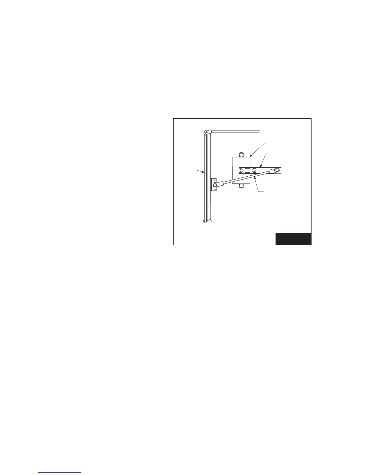
7. Move control arm to its open position as shown in Figure 9.
Note: Arm and connecting rod should
almost double over each other. This is
important for smooth operation and
longevity of the operator.
Note: Open position of gate may be
adjusted slightly with limit switch
adjustment, but when nished, open
position of control arm assembly should
be as close as possible to that shown in
Figure 9. If mechanical adjustments are
made to achieve desired open position
of gate, repeat Steps 6 & 7, since this will
aect the closed position.
8. When the desired open and closed gate position have been achieved, place gate in the
fully closed position and remove control arm extension from control arm. See Figure 6.
9. Remove control arm from operator drive shaft and insert drive key. See Figure 6.
10. Replace control arm on operator drive shaft with drive key and secure with 3/8 inch bolt.
See Figure 6.
11. Replace control arm extension on control arm and secure with hand knobs as shown in
Figure 6.
GATE
OPERATOR
CONNECTING
ROD ASSEMBLY
CONTROL ARM
ASSEMBLY
FIGURE 9
12. By turning the internal drive pulley by hand, move the control arm to somewhere in
its normal drive segment.
13. Control arm extension may now be attached to control arm as in Figure 6.
Note: If operator was ordered as a right or left hand unit from the factory, the control
arm position will be somewhere in its normal travel segment and the limit switches will
be set at an approximate open and close position. Final adjustments will be made later
after power is connected.
If the hand of the operator is to be changed in the eld as described in the following
section than before the control arm extension is replaced as in Step #11, proceed to
Step #12.