18
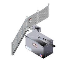
MASTER-SLAVE INSTALLATION
NOTE: A single unit is considered a
Master. In a Master/Slave installation,
one unit must be converted to LEFT
HAND operation.
1. Place jumper on the Master
operator’s control board in the
OFF position.
2. Place jumper on the Slave operator’s
control board in the ON position.
3. Connect Terminal #15 of Master unit
to Terminal #5 of Slave unit.
4. Connect Terminal #16 from the
Master unit to Terminal #6 on the
Slave unit.
5. Connect Terminal #17 from the Master unit to Terminal #7 on the Slave unit.
SLAVE POSITION
(ON)
MASTER POSITION
(OFF)
JUMPER
JUMPER
ON
SLAVESLAVE
ON
FIGURE 12
MASTER
SLAVE
15
14
1312
1198
765
4
321
10
16 17 18
15
14
1312
1198
765
4
321
10
16 17 18
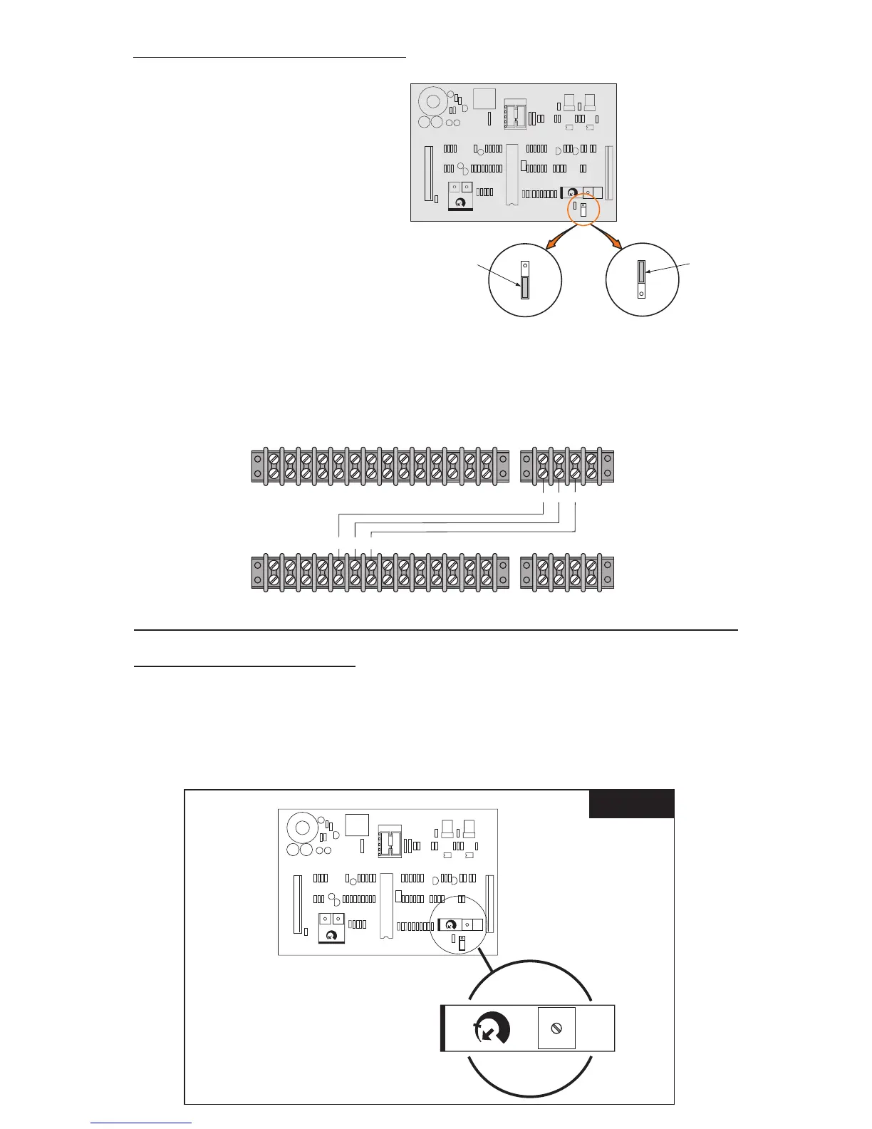
TIMER TO CLOSE OPTION
The operator is equipped with a timer to close option for use with control devices, such as a
radio control or card key control. The AUTO RE-CLOSE TIMER adjustment screw is located on
the printed circuit board. The operator is shipped from the factory with this timer preset to
the OFF position, fully counter-clockwise. As the timer adjustment screw is rotated clockwise,
the closing of the gate can be delayed from 2 seconds to 60 seconds.
LOCATION OF AUTO CLOSE
TIMER ADJUSTMENT
2 SEC
OFF
AUTO
CLOSE
TIMER
60 SEC