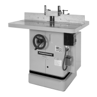
RECEIVING THE SHAPER
Remove the shaper assembly from its respective
shipping cartons and inspect for damage. Any
damage should be reported to your distributor and
shipping agent immediately.
Before proceeding further, read your manuals thor-
oughly to familiarize yourself with proper assem-
bly, operation, set-up, maintenance and safety
procedures.
INSTALLATION
Tools required:
screwdriver, adjustable wrench, Allen wrenches,
spindle wrench (provided), quill wrench (provided).
If you are mounting the shaper to the floor, use
high quality anchor bolts attached through the
mounting holes
on
the inside corners of the base.
If using a mobile base, be sure to lock the wheels
before assembling, operating or making adjust-
ments to the
shapero
BELT TENSION
Attach the drive belt as follows:
Loosen the two hex head cap screws (A) that hold
the motor base to the quill side, and slide the mo-
tor base towards the quill (B), Figure
8.
Attach
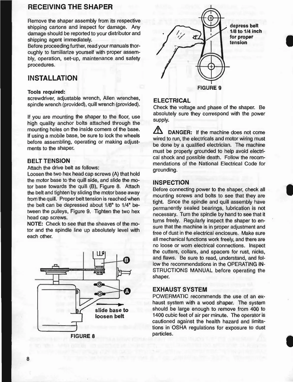
the belt and tighten by sliding the motor base away
from the quill. Proper belt tension is reached when
the belt can
be
depressed about
1/8"
to
1/4"
be-
tween the pulleys, Figure
9.
Tighten the two hex
head cap screws.
NOTE: Check to see that the sheaves of the mo-
tor and the spindle line up absolutely level with
each other.
FIGURE 8
8
slide
base
to
loosen
belt
FIGURE 9
ELECTRICAL
depress belt
. 1/8
to
1/4 inch
for
proper
tension
Check the voltage and phase of the
shapero
Be
absolutely sure they correspond with the power
supply.
& DANGER: If the machine does not come
wired to run, the electricals and motor wiring must
be done by a qualified electrician. The machine
must
be
properly grounded to help avoid electri-
cal shock and possible death. Follow the recom-
mendations
of
the National Electrical Code for
grounding.
INSPECTION
Before connecting power to the shaper, check all
mounting screws and bolts to see that they are
tight. Since the spindle and quill assembly have
permanently sealed bearings, lubrication is
n~t
necessary. Turn the spindle by hand to see that
It
turns freely. Regularly inspect the shaper to en-
sure that the machine is
in
proper adjustment and
free of dust
in
the electrical enclosure. Make sure
all mechanical functions work freely, and there are
no loose or worn electrical connections. Inspect
the cutters, collars, and spacers for rust, nicks,
and flaws.
Be
sure to read, understand, and fol-
low the recommendations
in
the OPERATING IN-
STRUCTIONS
MANUAL
before operating the
shapero
EXHAUST SYSTEM
POWERMATIC recommends the use of an ex-
haust system with a wood
shapero
The system
should be large enough to remove from 400 to
1400 cubic feet of air per minute. The operator
is
cautioned against the health hazard and limita-
tions
in
OSHA regulations
for
exposure to dust
particles.
I
•
•
 Loading...