10
It is essential that the mains water supply pressure and flow
availability are capable of meeting both the hot and cold water
services demand. The unit is capable of delivering up to 12
litres/min (140) or 18 litres/min (155x) of hot water. Where the
mains pressure is in excess of 6 bar, pressure reduction to
between 2 to 3 bar is recommended for splash free tap operation.
Unless consistently high mains pressures are available, it is
unlikely that a mains service pipe of less than 22mm OD
(copper) or 25mm OD (Blue MDPE) will provide an adequate
flow rate to the system. Powermax is not recommended for use
where the prevailing mains pressure is below 1.0 bar.
A full way isolating valve (e.g. gate valve or quarter-turn valve)
should be fitted in the supply before, but adjacent to, the unit.
It is recommended that a 22mm draw-off is provided from which
15mm or smaller pipes can then be used to supply hot water
services to individual terminations to give a balanced
distribution system.
Taps: Ensure that all terminal fittings will withstand mains
pressure.
Showers: Because of the draw-off profile, thermostatic shower
mixers are recommended to optimise performance; these must
be suitable for use at mains pressure. The Range ‘Showermax’
thermostatic shower kit is recommended for use with this boiler.
Where it is possible for a flexible shower handset to reach
below the bath spillover level, compliance with the Water
Byelaws is essential.
In areas where temporary hardness exceeds 200mg/L,
treatment of the mains water supplied to the appliance is
recommended to maintain its performance. The Powermax
electronic water conditioner P3237 is available factory fitted or
can be retro-fitted. Any scale reducer, or ion-exchange softener,
will be most effective when installed immediately upstream of
the boiler i.e. in the inlet pipework.
Good quality polyphosphate dosing devices can also inhibit
scaling but generally should not be fitted where heat could
impair their performance. Always follow the manufacturer’s
instructions.
Record the type of conditioner being used in log book.
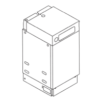
FLOW AND RETURN CONNECTIONS
These are on the LH side of the unit; the flow is taken from
below the pump. Pipework can be run inside the casing but
must not prevent the removal of the flue collector sump –
see NO GO area in Fig. 11.1. See also the plumbing layout
Guide on page 23.
PRIMARY SYSTEM
Use in Hard Water Areas
Terminal Water Fittings
Mains Supply Requirements
11 WATER SUPPLY
Fig. 11.1 Water connections
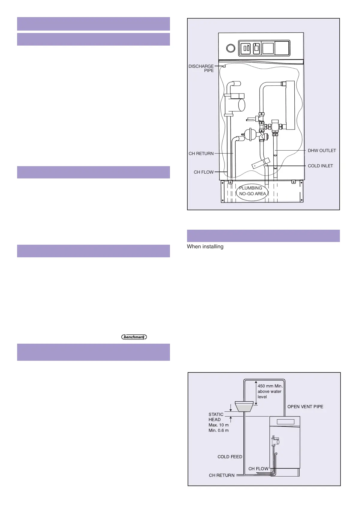
Fig. 11.2a
When installing ‘OV’ variants of Powermax the thermal store
within the appliance must be supplied with primary water from a
low pressure source e.g. a feed and expansion (F&E) cistern.
The unit is suitable for a maximum working head of 10 metres
(33ft head). The minimum static head is 600mm.
The vent pipe connection is situated at the top of the unit.
A 22mm open vent pipe must rise continuously, unimpeded, to
above the feed and expansion cistern. The top rear panel is cut
away to enable the vent pipe to run on the wall behind the
appliance.
Note also that the F & E water level must be at least 1metre
above the highest point of the primary circulation system.
An unvalved feed and expansion pipe must be provided from
the F & E cistern and teed into the C.H. return near the boiler.
Use 22mm if plastics pipe is used or if head is less than 1m.
Open Vented Systems
PIPEWORK ABOVE BOILER
Where the boiler has pipework rising above it, a non-return
valve should be fitted, preferably in the flow where it will not
obstruct filling.
Air vents must be fitted at the highest positions on flow and
return pipes and at any point where air is likely to collect.
TRVs IN SYSTEM
When all radiators are fitted with Thermostatic Radiator Valves,
a bypass loop (manual or automatic) must be provided.
SOLDER FLUX
Use water soluble flux for making soldered capillary joints in the
primary circuit. Traditional grease-based flux must not be used.
 Loading...