14
a With no water pressure on the system , check and if
necessary adjust expansion vessel pressure to 0.6 to 0.7
bar (8 to 10 psi) N.B. Vessel pressure cannot be
accurately set with water pressure in system.
b Loosen cap on automatic air vent, check draincock is
closed and open isolating valves on CH pump.
c Open stopvalve(s) and fill system with water to approx.
0.9 bar. Release air from radiators and pipework and run
cylinder up to temperature with CH off.
Bleed both heat exchanger and CH pumps.
d Thoroughly check radiator valve connections, glands
and unions for leaks.
e Set CH pump to speed 3, bleed every radiator and
pipework high points until all air or air/water mix is
removed.
f Allow system to reach full temperature (boiler ‘stat
switches off) and note HOT system pressure. Check that
relief valve is not “passing” by observing tundish over
several minutes.(“Passing” is usually due to debris on
valve seat. Snapping valve shut several times will
normally cure this). After firing and checking, drain and
flush the system, refill as above adding inhibitor, and
check for leaks.
g Again bleed every radiator etc. until all air or air/water
mix is removed and re check relief valve.
h Check system final pressure equals HOT pressure noted
in f above. Top up pressure if necessary.
i Adjust CH pump to correct speed for system. Remove
flexible hose and leave in a secure position for
householder. Protect hose union threads with end caps.
a Ensure Draincock is closed.
b Open valves either side of central heating pump .
c Admit water to the F&E cistern and thence to the
thermal store and the remainder of the central heating
system. Bleed both heat exchanger and CH pumps.
d Open any radiator valves and air bleed valves so as to
ensure that the store and radiators are full.
Note: Drain and flush the system. Refill as above adding
inhibitor, and check for leaks.
a Open one or more hot water taps.
b Turn on mains water supply and observe air free water
issuing from tap(s).
c Close tap(s) and check mains water pipework for leaks.
d Check that all factory-made plumbing connections
are tight (and have not loosened in transit).
e The blending valve is pre-set to supply water at
approximately 57°C and does not require adjustment.
CHECK POLARITY OF ELECTRICAL SUPPLY IS CORRECT.
CHECK THERMOSTAT WIRING, ie ‘SWITCHED’ WIRE IS
CONNECTED TO TERMINAL 28.
Remove screw from solenoid valve inlet pressure test point
Fig.13.4 and attach a suitable gauge.
a Turn any in-line gascock ‘on’ and turn the service
gascock ‘on’.(Indicated by the screwdriver slot being in
line with the direction of gas flow.) See Fig.12.3.
Starting (Lighting) The Appliance
Domestic Hot Water System
Open Vented Primary System
Sealed Primary System
12. COMMISSIONING
WARNING: DO NOT ATTEMPT TO START THIS APPLIANCE
UNLESS THE THERMAL STORE (PRIMARY CIRCUIT) HAS
BEEN FILLED WITH WATER
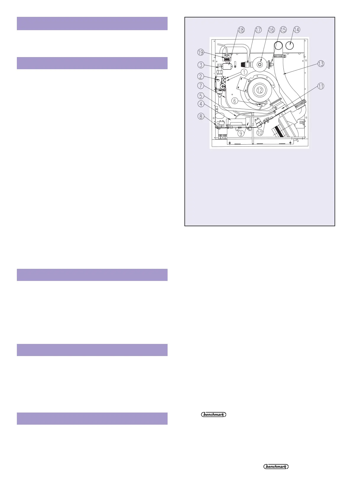
Fig. 12.1
1. Pressure Test Screws
2. Air-gas Ratio Valve
3. Union Gascock
4. Ignition Controller
5. H.T. Lead
6. Ignition Electrode
7. Air Sense Tube
8. Boiler Thermostat
9. Capacitor
10. Cold Start Thermostat
11. Injector
12. Burner
13. Air Inlet Pipe
14. Flue Pipe
15. Water Level Switch
16. Auto. Air Vent
17. Safety Relief Valve
18. EMC Filter
19. User Terminal
b Switch electricity supply on at the isolating switch and
observe orange neon on control panel indicating the
mains supply is live.
Note: Switch panel layouts are shown in Fig.12.4 for standard
model and Fig.12.5 for model with built-in programmer.
c Move the appliance on-off switch to the ‘I’ (on) position
(standard model) or ‘CONT’ (programmer model). Fan
starts to rotate after a slight delay. After a few seconds
the automatic ignition sequence will be initiated and the
burner will light.
d Green neon indicates the burner is operating.
Note: If the burner fails to light, the ignition sequence will be
automatically repeated until either the burner lights or a
safety LOCK-OUT condition is signalled by the red
neon. If red neon glows, switch to ‘O’ (OFF) at the
appliance on/off switch, WAIT TEN SECONDS
BEFORE SWITCHING ON AGAIN.
e With the appliance operating check the green neon is stable.
Note: After first filling with cold water some noise may
occur within the combustion chamber as the flame
settles on the burner. This is normal and will disappear
after approximately one minute. It does not occur in
normal use.
f Run boiler for 15-20 mins and transfer manometer tube
to outlet test nipple. Check burner pressure is
approximately 3.8 to 4.4 mbar (140) or 4.8 to 5.5 mbar
(155x). NB The longer the flue system the lower will be
the expected pressure. Record operating pressure in
log book. Very low values e.g. 3.0 mbar,
indicate an obstruction in the air supply; a high pressure
e.g. >6.0 mbar indicates a blockage in the flue pipe or
sump - see fault finder chart on page 12. Note that the
gas valve is factory pre-set and the burner pressure is
not directly adjustable. In case of difficulty consult The
Technical Helpline 0870 606 0955
g Record the “working” inlet gas pressure at inlet pressure
test nipple – Fig. 13.4 – in log book.
h Turn appliance off, remove gauge, replace test screws
and test for gas soundness.
 Loading...