MAX. No OF BENDS (90° or 135°) MAX. PIPE LENGTH
Air Inlet Flue Total Air/Flue inc. Terminal.
4 3 7 5.0m each
3 2 5 7.0m each
2 1 3 9.0m each
20
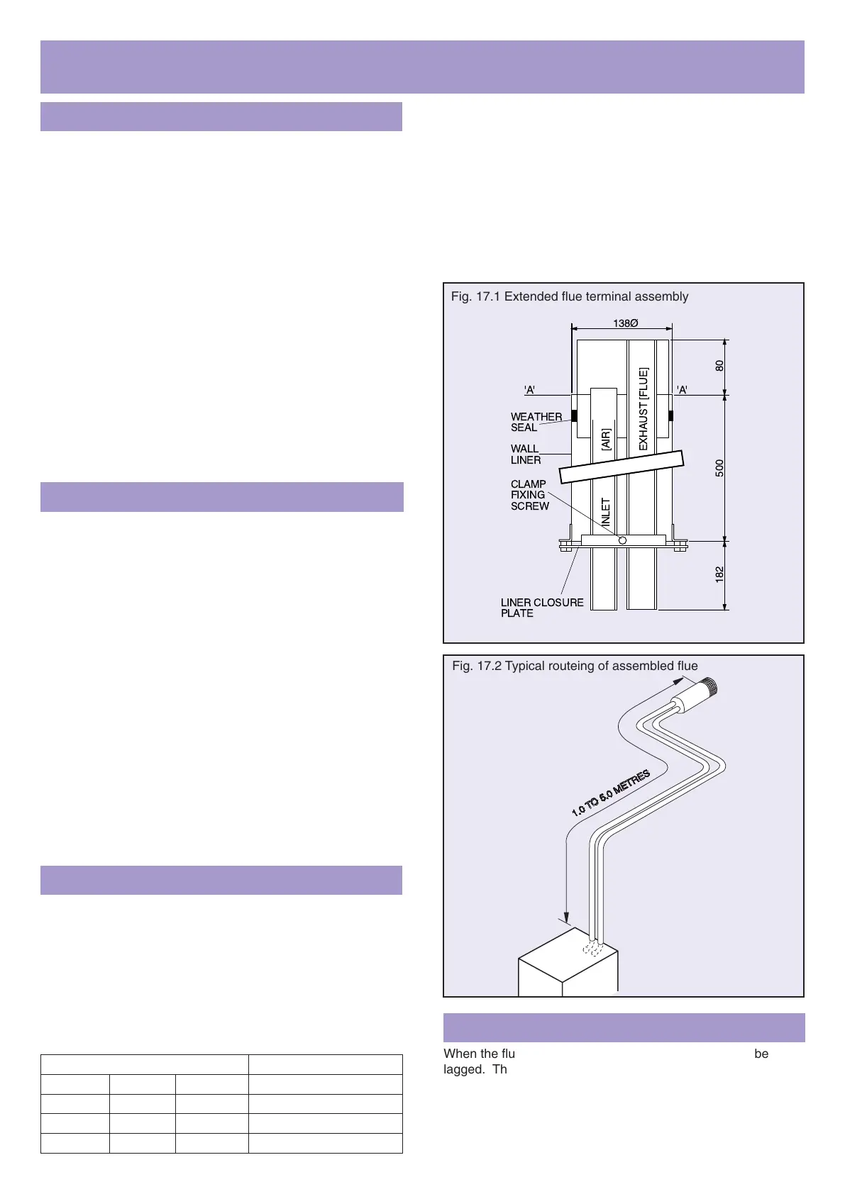
Installing Terminal Assembly
Note: The flue terminal must be installed horizontally.
a Mark the centre of the 140mm (5
1
/
2
inch) diameter hole
and core drill.
Note: If the wall is clad with a combustible material an
additional 25mm wide area must be removed around
liner.
Measure the wall thickness and cut the liner to this
length. Cut opposite end to lugs.
b Fit the liner through the 140mm diameter hole, lugs
inside, and make good internal and external rendering.
The latter may be done with arm extended through liner.
Note: Ensure lugs are either vertical or horizontal and
avoid filling threads in lugs with mortar.
c Mark wall thickness measurement on terminal air/flue
pipes using datum ‘A’ ‘A’ shown in Fig. 17.1. Fix liner
closure plate on to the pipes at this length using the
clamp attached. Avoid crushing pipes with clamp. If
either pipe requires cutting to length (eg to allow bends
to be fitted) do this now.
d Push flue terminal assembly into liner. Secure terminal
by fixing plate to liner using the screws supplied.
17. INSTALLATION INSTRUCTIONS FOR EXTENDED BALANCED
FLUE SYSTEMS
Routeing of Air/Flue Pipes
For flue and air pipes leaving the boiler vertically, refer to the
plan view in Fig. 17.7 (especially when planning to first fix the
extended pipes).
a Measure distances of flue pipe runs and note as a guide
to cutting pipes. The maximum length of each air/flue
pipe run must not exceed 5.0m (including a Horizontal
BF Terminal) if the maximum of 4 air pipe bends and 3
flue pipe bends is used – see Fig.17.2. There is no
minimum length.
If fewer bends are used between the appliance and the
flue terminal, then the maximum length of straight pipe
can be increased if required – see table below.
Any exhaust flue pipe accessible to occupiers of the
dwelling must be covered with protective ducts – Part
No. P360 is suitable.
The flue terminal assembly and the (hot) exhaust
products flue pipe must not be closer than 25mm (1") to
combustible material. If the flue pipes are run through a
timber wall or cupboard, or via a roof space with
wooden rafters; ENSURE A 25mm GAP IS LEFT
AROUND THE EXHAUST FLUE PIPE; OR EXTEND
THE PROTECTIVE DUCT.
Preparing Appliance & Protective Duct
a See Fig. 17.3. Slip a worm drive clip over both ends of
flexible inlet duct. Push one end of the duct over the
spigot on fan inlet and secure with clip.
If flue pipework leaves appliance vertically, remove 90°
elbow from flue pipe and engage plain end with flexible
duct. Secure with worm drive clip.
Insert flue pipe extension adaptor P338 into flue pipe
socket on boiler. Re-fit rear box (This can not be fitted
after vertical flue pipe has been fixed).
Note: If air/flue pipes run horizontally leftwards, align
bends and fit the first pipe length to the left, before
securing clamp with 70mm long screw.
b Move appliance to its final position. Note: Fixing the first
stage of the open vent pipe and F & E pipe is
recommended next (See section 11 of main instructions).
c With appliance in position, determine length of
protective duct required and if necessary adjust
standard length to suit – See Fig 17.5. Fix duct to wall
with screws and plugs provided. Temporarily set aside
duct cover.
 Loading...