8
Wiring must comply with the current IEE Wiring Regulations.
The supply cable must be 3-core 0.75sq.mm (24/0.2mm) to
BS6500 Table 16.
The supply must be of 230V ~ 50Hz. A 3A fused double pole
isolating switch may be used, having a minimum contact
separation of 3mm in both poles, providing it serves only the
boiler and its system controls. Alternatively a 3A 3 pin fused
plug may be used.
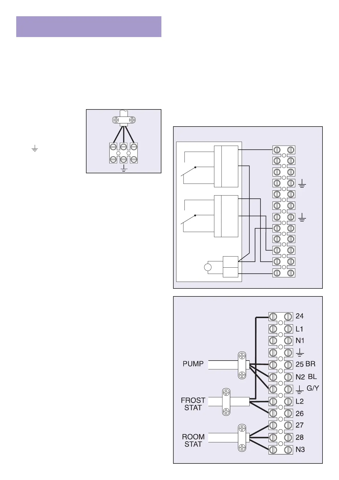
Wiring diagrams are shown in Fig 10.1 for standard model and
Fig 10.2 for model with built-in programmer. Note that the water
level switch is omitted on open vented models.
1. Connect the incoming
electricity supply
cable to terminals
L – brown
N – blue
- green-yellow
of the user terminal
block. Ensure that the
cable is routed via the
anchorage and through
bushing in LH side panel. See Fig. 9.6. Trim all excess
length from main supply cable.
2. Connect any external control cable to the terminal block
as indicated and described below – See Fig 10.4 – and
route via unused grommets on lower LH side of unit.
Note. The length of the conductors between the cord
anchorage and the terminals must be such that the
current carrying conductors become taut before the
earth conductor if the cable is tugged, ie the earth wire
must be longer than both the live and neutral when
connecting into the terminal block.
3. To wire a room thermostat, remove orange link wire from
terminals 27 and 28. Connect the feed wire to the stat to
terminal 27, connect the switched wire to terminal 28
and the neutral to N3.
4a. To provide time to control for models without the built-in
programmer, we recommend using the Powermax
‘Diadem’ analogue programmer kit P4230. To install
remove the slave plug – see Fig 12.2 – and replace with
the plug-and-lead supplied. Fixing instructions for the
‘Diadem’ programmer are supplied in the kit.
4b. Alternatively choose a twin channel programmer that has
volt free contacts, as provided by programmers which
use the British Gas standard wall plate configuration and
a pumped/gravity option which should be set to “gravity”.
See Fig. 10.3. Power the programmer from terminal L2
and link to one side of the programmer’s hot water relay
contacts. Connect the switched hot water contact to
terminal 24. To wire the central heating channel, remove
link wire (terminals 27 and 28) and connect the
programmer’s CH relay contacts to terminals 27 and 28.
NB The appliance switch must be kept in the OFF
position otherwise the DHW remains permanently
switched on. The central heating switch should be ON to
obtain timed switching.
5. If a combined clock thermostat is being used to control
the central heating, it should be of a type having voltage
free contacts. Remove link wire (terminals 27 and 28)
and connect the switched wire to terminal 28, feed wire
to terminal 27.
A permanent live is available at terminal L2 and
additional neutral at terminal N3 for supplying power to
the clock.
10. ELECTRICAL CONNECTION
TO THE APPLIANCE
6. If a frost ‘stat is required, this should have voltage free
contacts and provide a single pole double outlet.
Connect as follows:
Frost ‘stat live to terminal L2
Output 1 to terminal 24
Output 2 to terminal 26
The Sopac-Jaeger TA 547-04 (Double Outlet) is a
suitable frost protection thermostat.
7. After completing the electrical connections, perform the
following electrical system safety checks:
A – EARTH CONTINUITY
B – POLARITY
C – RESISTANCE TO EARTH
D – SHORT CIRCUIT
WARNING – THIS APPLIANCE MUST BE
EARTHED
Fig. 10.4 Terminal block
 Loading...