4
Where the lowest part of the terminal is less than 2m (6ft) above
the level of any ground, balcony, flat roof or place to which
people have access, the terminal must be protected by a guard
of durable material. A Terminal Guard Kit is available as an
optional extra Part No. P210 from Baxi UK. The guard requires
a flat wall surface of approximately 450mm diameter,concentric
with the terminal assembly.
The exhaust flue pipe of the terminal must not be closer than
25mm(1in) to combustible material. Additional clearance must
be provided when passing the flue through timber walls.
Advice on gas installations in timber framed buildings is
contained in an IGE technical publication available from the
Institution of Gas Engineers, 21 Portland Place, London W1N 2AF.
Several flueing systems are available. ALL are ‘room sealed’
and a choice of terminals is offered:
1. Horizontal balanced flue terminal.
2. Vertical balanced flue terminal.
3. Ridge tile terminal (unbalanced)
4. Mini terminal balanced flue systems
All terminals can be sited up to 7.0m from the boiler. In some
circumstances, a horizontal terminal can be sited 9.0m from the
boiler – See below. Flue systems are supplied in kits, or
components can be ordered individually-see list in section 17.
Before starting an installation, check that the correct flue
kit has been supplied with the boiler.
The efficient operation of Powermax will naturally give rise to
condensation in the flue gases and pluming will be visible
during adverse atmospheric conditions. In installations with long
flue runs some condensate may be discharged from the
terminal. The terminal must, therefore, be sited to avoid
nuisance from either phenomenon.
Visible Pluming
6. FLUEING OPTIONS
Use Kit P260 for installations where the flue passes through the
wall immediately behind the appliance. The terminal is suitable
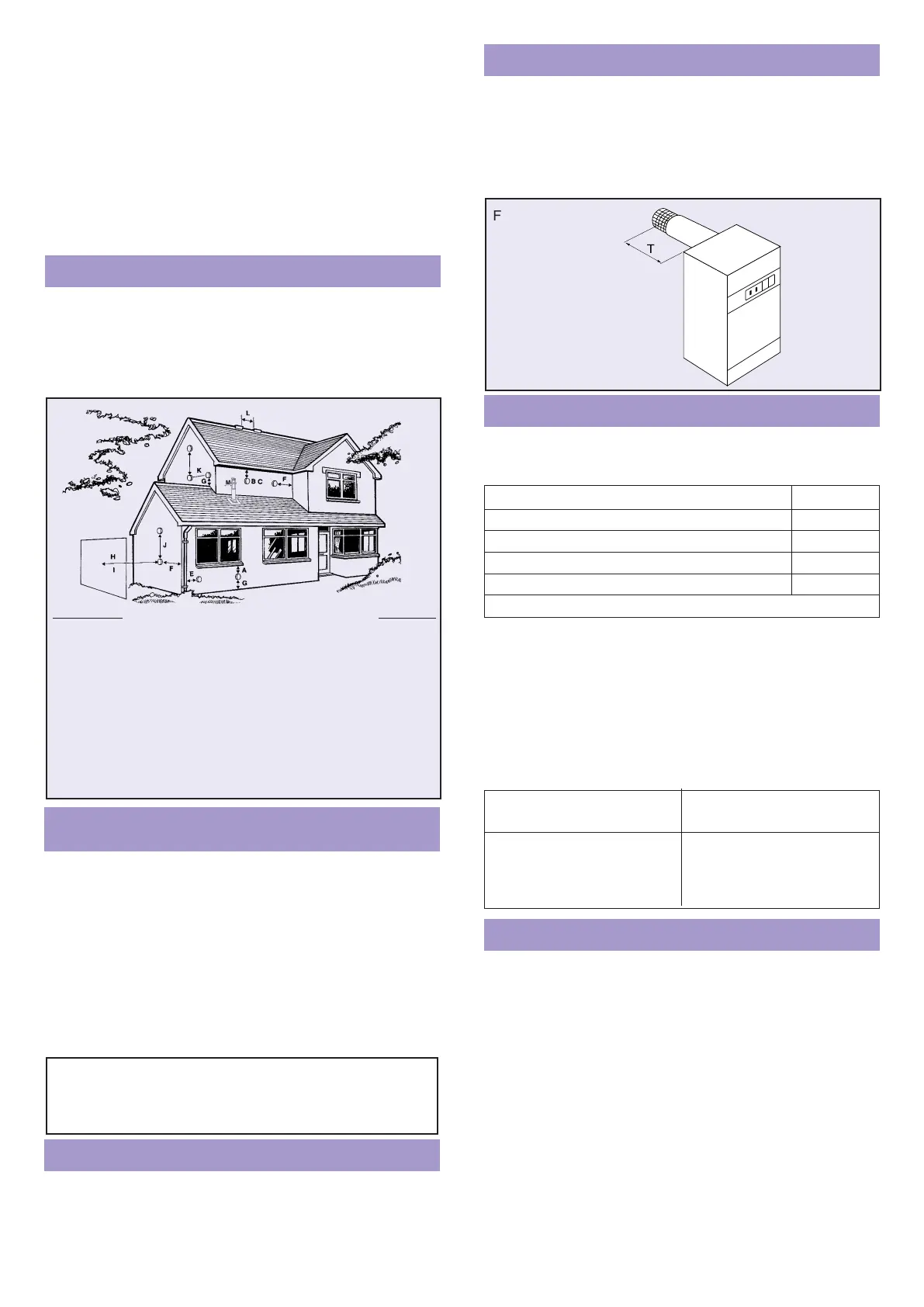
for a thickness of 200mm to 500mm as shown in Fig.6.1.
An 800mm wall liner P337 can be ordered separately.
Step-by-step instructions are given in Section 9.
Kits are supplied as follows with components also available
separately.
Kit No.
The maximum length of each air/flue pipe must not exceed 5m
(including a Horizontal BF Terminal) when the maximum of 4 air
pipe bends and 3 flue pipe bends is used – see Fig 6.3.
The pipes can leave the boiler horizontally to right or left, or
rearwards, or vertically upwards.
There is no minimum length.
If fewer bends are used between the appliance and the flue
terminal, the maximum length of straight pipe can be increased
if required – see table below.
Kit P242 allows the flue to terminate at an approved (gas vent)
Ridge Tile Terminal with combustion air being drawn from a
ventilated loft space or from a second ridge terminal. The inlet
terminal must be not less than 300mm above the top surface of
the ceiling insulation.The air inlet pipework must be at least
1.5m long and not less than half the flue length. Full fixing
instructions are supplied in each kit.
Additional components may be specified up to the maximum
indicated in the diagram and the table opposite.
Combustion air may be drawn from a ventilated roof space or
from a compartment or duct which is permanently ventilated
direct to outside air. The effective open area of the vent must
not be less than 160cm
2
(25in
2
).
When combustion air is drawn from a roof space or
compartment or duct, that area must be effectively sealed from
the remainder of the dwelling. A tight fitting trap door or similar
is acceptable.
Ridge Tile Terminal
Fig. 6.5
Extended Balanced Flue Systems
Fig. 6.3
Balanced Flue Terminal
1m Sideways horizontal balanced flue P261
3m Extended horizontal balanced flue P263
5m Extended horizontal balanced flue P265
7m Extended horizontal balanced flue P267
9m Extended horizontal balanced flue P269
Refer to Section 17 for step-by-step fixing instructions.
MAX. No OF BENDS MAXIMUM PIPE
(90° OR 135°) LENGTH
Air Inlet Exhaust Flue Total Air/Flue inc. Horizontal Trml.
4 3 7 5.0m each
3 2 5 7.0m each
2 1 3 9.0m each
Lagging is recommended when the flue pipe exceeds 3m. The
insulation used must be non-combustible and suitable for
operating at temperatures up to 200°C. Class ‘O’ foil backed
glass wool or mineral wool insulation wrapped tightly around
the flue pipe will help to reduce pluming. It is not necessary to
insulate the air inlet pipes.
Flue Pipe Insulation
Fig. 6.1
‘T’ WALL THICKNESS =
200mm MIN
500mm MAX
Terminal position Min. distance
A: Directly below an openable window or other opening, e.g. an air brick 300mm
B: Below gutters, soil pipes or drain pipes 75mm
C: Below eaves 200mm
D: Below balconies or car port roof (not illustrated) 200mm
E: From vertical drain pipes and soil pipes 75mm
F: From internal or external corners 300mm
G: Above ground or balcony level 300mm
H: From a surface facing a terminal 600mm
I: From a terminal facing a terminal, or from an opening in a car port into 1200mm
dwelling (not illustrated) 1500mm
J: Vertically from a terminal on the same wall 300mm
K: Horizontally from a terminal on the same wall 300mm
L: Between ridge terminals (if combustion air is drawn from second terminal) 300mm
M: Between vertical terminal and wall 300mm
NB: Terminals located less than 2m above ground level must be protected by a terminal
guard P210
Fig. 5.1
J
IMPORTANT Any flue pipework in a horizontal plane
MUST run downwards AWAY from the boiler by 5mm
per metre. To prevent water accumulation there must
be no sags or dips in the pipework.
 Loading...