5
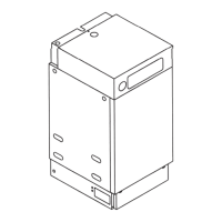
Fig. 6.2
Mini terminal
flue system
Example of rearwards
flueing to achieve
minimum 300mm
distance between
terminals
Maximum permitted flue run
of 9.0m total length (including
one 90° bend and one 170°
offset Bend in the flue pipe).
Fig. 6.3
Typical routeing of
extended balanced flue
Fig. 6.5
Typical routeing of
ridge terminal flue kit
Note that
the length of
the air inlet
pipe must not
be less than
0.5 x length
of flue pipe
1.5 TO 4.0 METRES
1.5 TO 5.0 METRES
[STANDARD KIT]
1.5 TO 7.0 METRES
[EXTENDED]
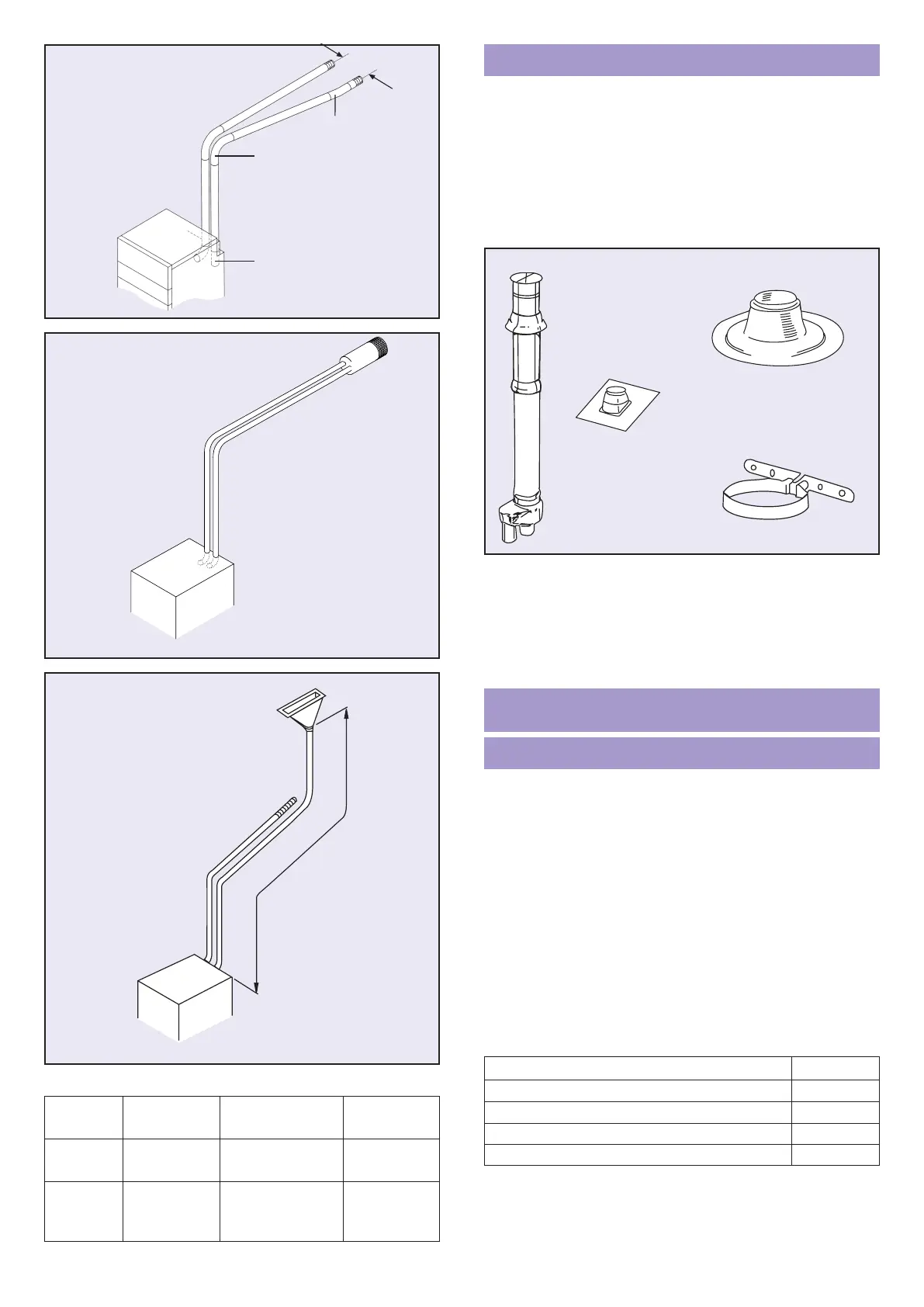
Vertical RS Flue System
The Powermax Vertical RS flue system offers an unobtrusive
balanced flue terminal as an option for both pitched and flat roofs.
The vertical roof terminal Part No. P230 provides a combined air
intake and combustion gas outlet in a concentric arrangement.
Below the roof the terminal changes into a twin pipe system.
Separate roof flashing units should be ordered (specified) for
pitched or flat roofs. Roof pitches from 15° to 55° are catered for
by selecting one of three pitched roof flashing units.
P231 for pitches 15° to 25° P232 for pitches 25° to 45°
P233 for pitches 35° to 55° P236 for flat roofs
To connect the Powermax to the vertical terminal a kit Part No.
P246 is required. This contains a range of extension air/flue
pipes and bends to enable the terminal to be sited up to 2.5m
from the appliance. The maximum overall length of the
complete flue system must not exceed the limits indicated for
extended balanced flue systems, however the length of the
vertical terminal itself can be disregarded. Complete fixing
instructions are provided in each kit.
The Mini Terminal Flue system provides an alternative
arrangement to the standard (140mm diameter) balanced flue
terminal.
Separate 65mm diameter air inlet and flue terminal assemblies
can be positioned in different locations on the same wall subject
to similar wind conditions. See Fig. 6.2.
They are available in a small range of colours chosen for their
compatibility with typical external building materials.
Code.
A Matt Black
(standard finish)
D Red Brick
B Stone
(also suitable for yellow stock brick)
E Slate
C Light Brick F White
Each terminal requires a hole of 65mm diameter to be core
drilled through the external wall.
Flue kits are available as listed below. Each kit contains all the
components needed for a complete system including full fixing
instructions.
Kit No.
* For sideways flueing
WARNING – The flue pipe becomes very hot when appliance
is working. Householders should be warned not to touch
exposed pipe e.g. beyond protective duct within loft.
The flue pipe should be insulated or ducted if accidental
contact is likely.
Description
MINI TERMINAL FLUE
P231/232/233
P230
P236
P234
Fig.6.6 VERTICAL FLUE COMPONENTS
FLUEING RESTRICTIONS – RIDGE TILE TERMINAL
Number of Bends Pipe Length
Application Components 90° or 135° (metres)
Standard Air Inlet 2 1.5 minimum
Kit Flue 3 1.5 minimum
Extended Air Inlet 2-3 1.5 to 4.0
Inlet & Flue 3 max 1.5 to 7.0
Flue
1m Mini Terminal BF kit* P271
3m Mini Terminal BF kit P273
5m Mini Terminal BF kit P275
7m Mini Terminal BF kit P277
9m Mini Terminal BF kit P279
 Loading...