16
a Remove two M4 screws holding fan to burner, also air
inlet elbow retaining screws. Pull fan away from burner
and rest on ledge formed by cross brace. Disconnect air
sense tube and check that it remains supple and free
from splits etc. Release both union nuts on gas pipe.
Note: Hold injector with second 19mm AF spanner
to prevent injector being disturbed. Swing pipe clear
of burner.
b Loosen 8 screws around burner flange. Lift burner
gently upwards until ring clears the controls chassis.
Keep screws safe.
Gently remove deposits from burner face and inspect.
Renew burner flange gasket.
c Disconnect the HT lead at the electrode and check that
the connection is clean and tight. Inspect the electrode
condition and check gap which should be 3.5 to 4.0mm.
d Sealed system models only – release system pressure
via relief valve and check expansion vessel pre-charge
pressure is between 0.6 to 0.7 bar. Adjust if required
and top up system to same pressure. Remove air from
boiler via automatic air vent.
e Reassemble in reverse order ensuring all 8 burner/fan
screws are tight. Check that fan lead remains clear of
motor after re-assembly.
NB: Check tightness of burner screws again after
boiler has operated for several minutes.
Routine Annual Servicing
To ensure safe, efficient operation of the appliance, it is
necessary to carry out routine servicing at regular intervals.
The frequency of servicing will depend upon the particular
installation conditions and the use to which the boiler is put.
IMPORTANT: Before commencing any servicing or
exchange of components, always turn off the gas supply
and isolate the electricity supply.
An annual inspection is recommended with servicing every
other year.
After completing any service work always test for gas
soundness.
To gain access to the boiler for servicing, remove front panel
and top cover as described in section 9 and fig 9.1.
Note before removing any of the burner parts for servicing
ensure you have a new burner gasket P507 available.
13. SERVICING INSTRUCTIONS
Annually
Every Second Year
f Additionally to the above.
Use pliers to remove turbulators from heat exchanger
pipes. Visually inspect combustion chamber and pipes
for excess deposits (a small torch will be useful). If
cleaning is required, first remove sump – see step g.
g Remove M6 screw that secures the retaining strap and
withdraw strap. Allow sump to drop vertically to floor
level but leave underneath boiler to collect deposits.
h Heat exchanger tubes can now be cleaned using a
28mm (1
1
/
8
") diameter brush. Remove sump ensuring it
is clear of gauze in flue collector. Vacuum away deposits
and clean sump prior to replacing.
Note: Apply similar care when replacing sump, ensuring
it is evenly retained. Check sump joint for soundness
using an electronic ‘sniffer’ whilst boiler is operating.
i Check that boiler and its controls are functioning
correctly.
j Remove HW mini expansion vessel and probe bladder
using a blunt instrument. Replace if deflated, Part No. P527.
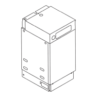
Fig. 13.1
Fig. 13.2
Combustion testing
A combustion analysis test point is provided on the flue
collector (just above sump joint). The test point is a tapped hole
and is sealed by a special screw/washer assembly. Insert the
sampling probe by approximately 25 to 30mm until it touches
the inner gauze. This will enable an accurate reading to be
taken. For a correctly installed appliance typical values to be
expected are:-
CO < 20ppm
CO
2
8.8 - 9.6%
Levels significantly outside these limits should be investigated
and may indicate a defective component or faulty installation.
Ensure the test point is FULLY GASTIGHT. Do not substitute
any other screw for the special Powermax screw
(Part No. P690).
Electrical safety testing
It may be necessary to carry out electrical test work to ensure
the safety of the appliance circuits after overhaul or as part of
an inspection programme. This should be carried out to latest
edition IEE regulations for Class 1 appliances with the flash test
set at 1500 volts.
140 TOP RETAINING
SCREWS
(ACCESSIBLE AFTER
REMOVING FRONT)
155x TOP PANEL
RETAINING SCREW
TRANSIT SCREW
FRONT PANEL FIXING
SCREWS
PLINTH FIXING
SCREWS
 Loading...