17
Air/Gas (Solenoid) Valve Fig.12.1 & 13.4
a Refer to General above.
b Disconnect gas service cock at the union and
disconnect the outlet pipe at the union nut on flared
fitting.
c Remove screw holding bracket. Disconnect the wiring
leads and remove valve. Remove bracket.
d Remove the flared fitting from valve outlet and transfer
to new valve. Note: Threads on valve outlet must be
resealed with a sealant complying to BS5952.
e Fit new valve in reverse order. Ensure that inlet and
outlet connections are fully gas tight.
Procedure for checking/setting S.I.T. Sigma 848 Air/Gas
Ratio Valve
Do not attempt these adjustments unless you have both
the use of a correct specification of digital manometer
and the relevant training.
i Using a differential manometer connect the positive side
of the manometer to the gas valve outlet pressure
tapping and the negative side to the air pressure sense
line using a tee piece.
ii Start the boiler, ensure that the inlet pressure is
adequate, i.e. ~20 mbar and bring thermal store up to
working temperature (above 60°C). Read the
differential pressure across the micromanometer (ΔP).
iii If reading is outside the range
_
0.13 to
_
0.16 mbar,
carefully remove the servo governor cap and adjust the
value of ΔP to
_
0.13 (±.03) mbar (i.e. the gas pressure
is 0.13mbar
less
than the air sense pressure) .
iv Replace cap and tighten.
v Re-connect sense line tubing to valve.
vi Check burner pressure is approximately 3.8 to 4.4 mbar
(140) or 4.8 to 5.5 mbar (155x). NB The longer the flue
system the lower will be the expected pressure. Very
low values e.g. 3.0 mbar, indicate an obstruction in the
air supply; a high pressure e.g. >6.0 mbar indicates a
blockage in the flue pipe or sump - see fault finder chart
on page 12. In case of difficulty, consult The Technical
Helpline 08706 049049.
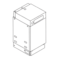
Fig. 13.3 ELECTRODE GAP
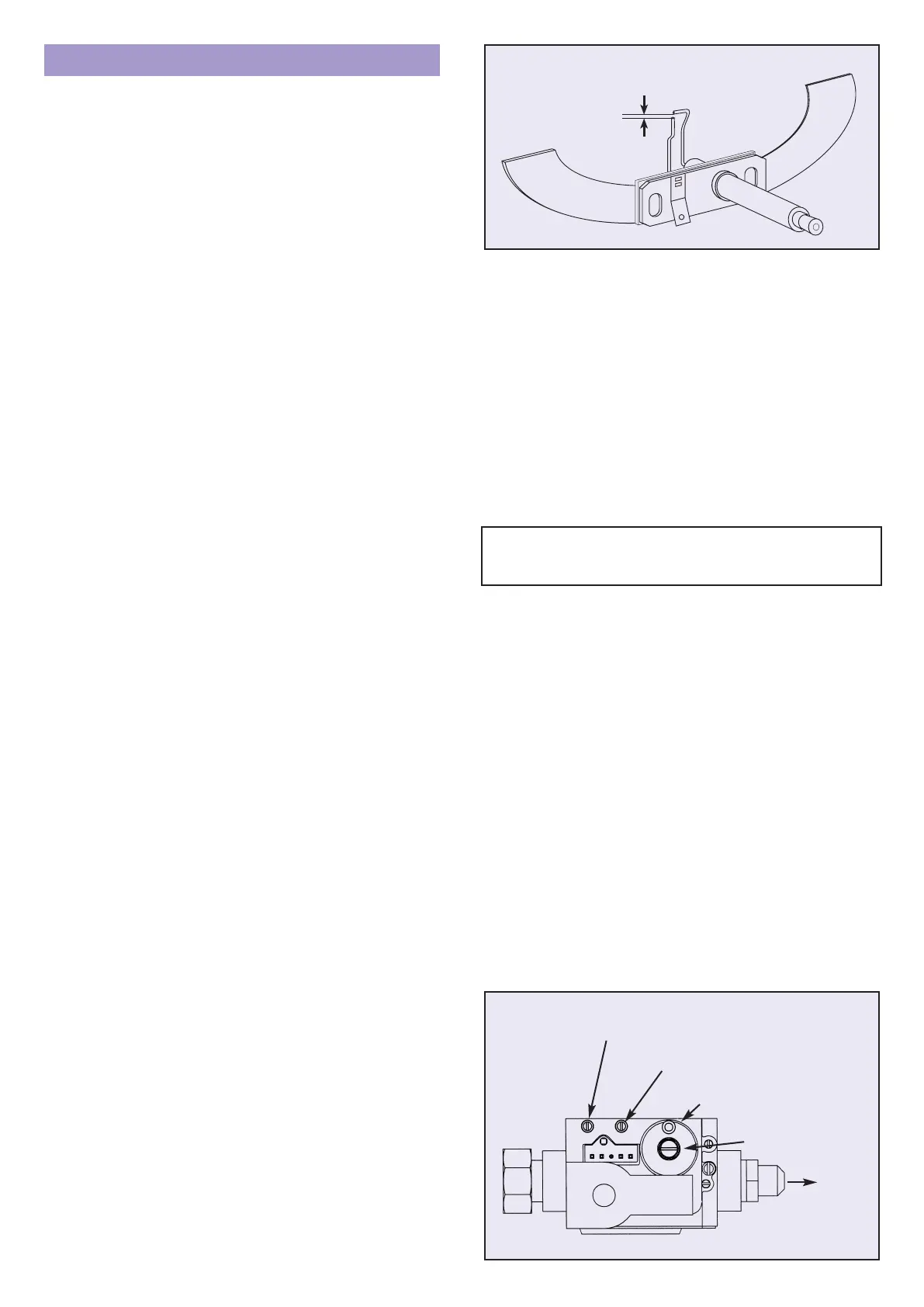
Fig. 13.4 S.I.T. SIGMA 848 AIR/GAS RATIO VALVE
Component Exchange Procedures
Fig. 13.1
General Notes
Isolate gas and electricity supplies. To gain access remove front
panel and top cover as described in section 9 and fig 9.1.
Components are replaced in reverse order unless otherwise
stated.
To remove switch panel undo the single fixing screw noting how
lower edge of panel locates for reassembly. Taking care not to
damage the wiring, the panel can be attached for servicing
through the 2 holes in its corners to the lid fixing nutserts using
the lid fixing screws.
Note that any damaged gasket or seal must always be
renewed.
Full Sequence Ignition Controller Fig.12.1
a Refer to General above.
b Pull off H/T lead from connection at top of controller.
c Pull out the ‘Molex’ connector plug.
d Remove top screws, and remove controller.
HT Lead Fig.12.1.
a Refer to General above.
b Disconnect lead at electrode and at ignition controller.
Burner Fig.13.2
a Refer to General above.
b Remove two M4 screws holding fan to burner, also air
inlet elbow retaining screws. Pull fan away from burner
and rest on ledge formed by cross brace. Disconnect air
sense tube and check that it remains supple and free
from splits etc. Release both union nuts on gas pipe.
Note: Hold injector with second 19mm AF spanner to
prevent injector being disturbed. Swing pipe clear of
burner.
c Remove 8 screws from burner flange and lift burner out.
Note: When re-tightening union nut on gas feed pipe
hold injector securely with second spanner to prevent it
being disturbed. Always fit new flange gasket P507.
d Check for soundness at gas supply pipe unions.
Injector
a Refer to General above.
b Release union nuts on gas feed pipe.
c Unscrew injector anti-clockwise. Re-seal new injector
with a sealant complying with BS 5952.
d Check joints for soundness.
Spark Electrode Fig.13.3.
a Refer to General and Burner above.
b. Remove burner/fan.
c Disconnect the H/T lead. Remove the screws and
washers. Gently pull the electrode away from the
combustion chamber. Fit new electrode and gasket and
check that the spark gap is as shown.
d Replace burner using new gasket, and check
operation of appliance.
e Check for soundness at gas supply pipe unions.
Fan Fig.12.1 & 12.2
a Refer to General above.
b Disconnect fan leads from small terminal block.
c Remove screws retaining air inlet elbow. NB 2mm A/F
hexagon key required.
d Remove two M4 screws and pull the fan gently forward.
e Ensure fan is fitted with new O-ring supplied.
Reassemble and check for soundness, especially air
inlet elbow.
Neon Lights and Switches Fig.12.2
a Refer to General above.
b Push the neon light or switch from the back through the
switch panel and replace in reverse order making sure
the leads are correctly replaced – See wiring diagrams
Fig.10.
OUTLET PRESSURE TEST NIPPLE
AIR SENSE NIPPLE
GOVERNER CAP
INLET PRESSURE TEST NIPPLE
OUTLET
 Loading...