PRELIMINARY
7
E
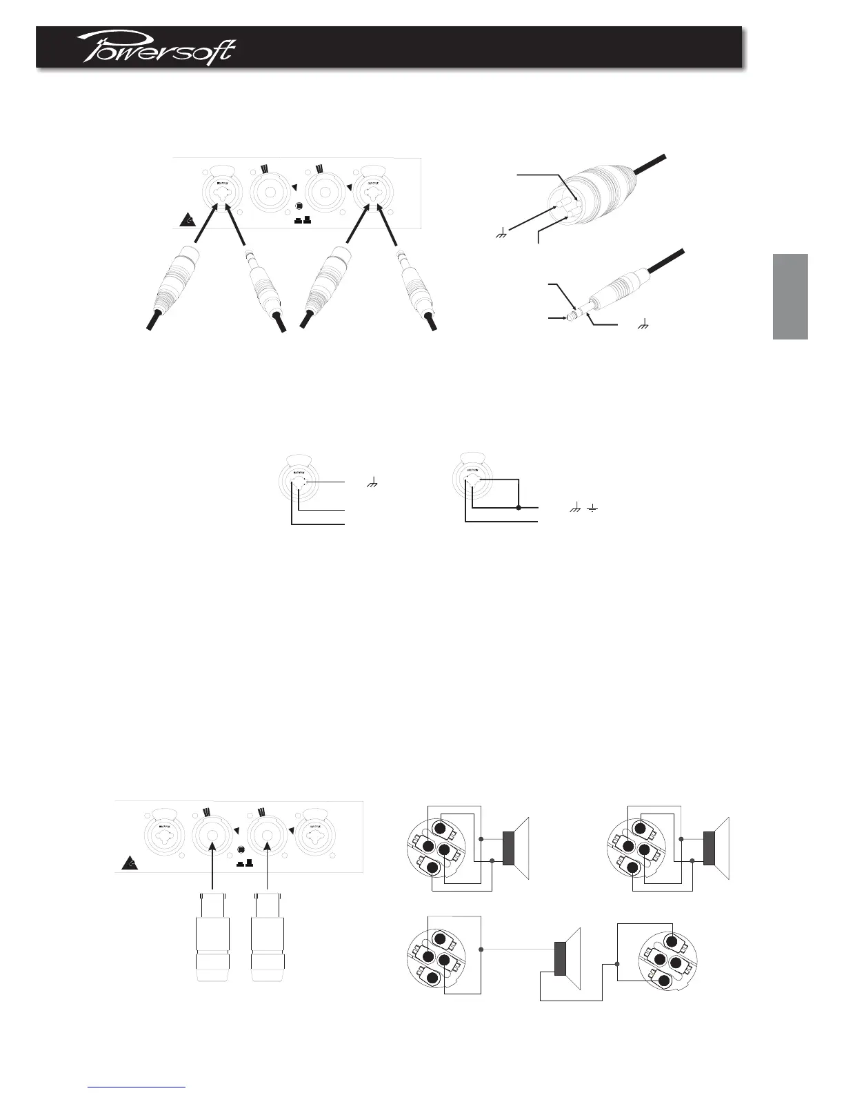
1.5ConnectingInputs.Inputconnectionsaremadeviathe3-pinXLR-femaletypeor1/4"phoneJackconnectorsonthe
rearsideoftheamplifier. Thepolarityisshowninfigure1.5.1.
figure1.5.1
OUT2
IN2 IN1
OUT1
T
U
R
N
T
O
L
O
C
K
T
U
R
N
T
O
L
O
C
K
“WARNING
To reduce The Risk of Fire
or Electric Shock, do not
Expose this Apparatus
to Rain or Moisture”
LINK
ON OFF
CLASS2WIRING
IN(+)
IN(-)
GND
IN(+)
IN(-)
GND
Thefigurebelowshowstheconnectionofanaloginputforbalancedandunbalancedline. Youcanusebothconfiguration,
butyoumustconsiderthatunbalancedlonglinecanintroducenoiseintheaudiosystem. TheLinkswitchlocatedinthe
rearpanelisfordirectparallelingtherearinputconnectors. Youcanusetheremaininginputconnectortocarrysignalto
otheramps.
IN(-)
IN(+)
GND
Balancedinput
IN(+)
SHIELD
Unbalancedinput
/
figure1.5.2
1.6ConnectingOutputs
Warning:therearelethalvoltagesattheloudspeakerconnectorswhentheamplifieristurnedon.Topreventany
damagesturntheamplifieroffbeforeconnectingtheloudspeaker
Outputconnectorsaremadevianeutrikspeakonconnectors.Consultthewiregaugecharttofindasuitablewiregaugeto
minimizepoweranddampingfactorlossesinthespeakercables. Theoutputscanalsoworkonbridgemode.Foreach
devicethe1+and2+pinsofspeakonconnectorareconnectedinsideandhavetobeconsideredthepositiveoutputofthe
channel;the1-and2-pinsofspeakonconnectorareconnectedinsideandhavetobeconsideredthenegativeoutputof
thechannel.
Note:ChannelBisalwayspolarityreversedoutputstage,butpolaritycompensatedbyfeedingtheminuspinsofthe
channelBoutputwiththeoutputvoltage.Channel A isconnectedinthepolaritymode.Byhavingchannel A andB
operatinginoppositepolarity,theenergystorageinthepowersupplyismoreefficient. Thisissignificantforsignalsbelow
100Hz(subbassetc.)andimprovesthepowerbandwidth. Besuretousebalancedinputsonallmeasurement
equipment(alsooscillatorprobes)inyouarebenchtesting.
figure1.6.1
OUT2
IN2 IN1
OUT1
T
U
R
N
T
O
L
O
C
K
T
U
R
N
T
O
L
O
C
K
“WARNING
To reduce The Risk of Fire
or Electric Shock, do not
Expose this Apparatus
to Rain or Moisture”
LINK
ON OFF
CLASS2WIRING
CH1
OUT
stereomode
bridgemode
+
_
2+
2-
1-
1+
CH2
OUT
+
_
2+
2-
1-
1+
CH1
OUT
+
_
2+
2-
1-
1+
CH2
OUT
2+
2-
1-
1+