5
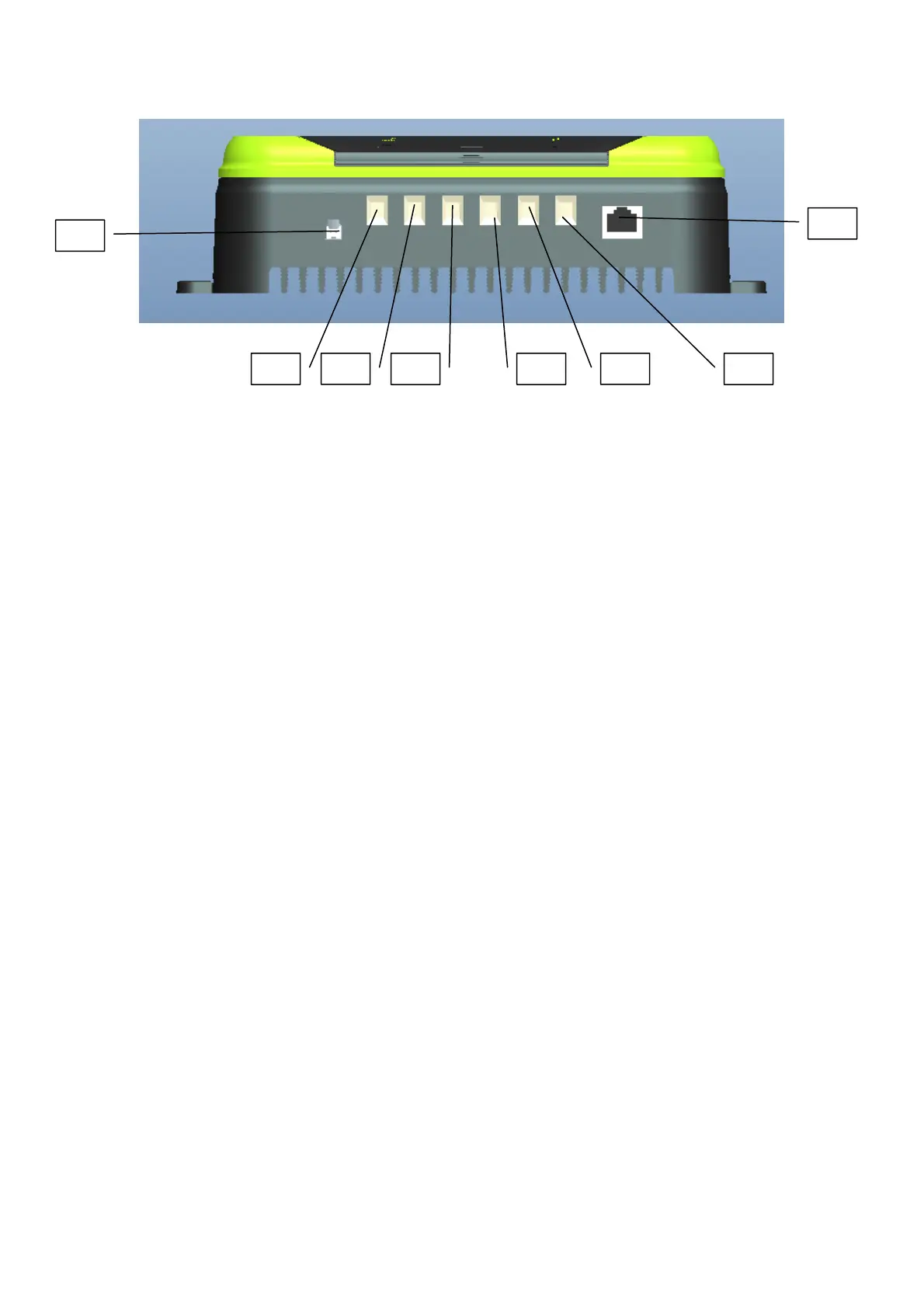
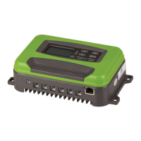
(Fig. 2)
9. External temperature probe
10. RJ45 port, connected to the remote control board through the network cable and
synchronized with the LCD screen (this port is reserved and the remote control board is oponal)
11. PV+ (connected to the posive electrode of the solar panel)
12. PV- (connected to the negave electrode of the solar panel)
13. B+ (connected to the posive electrode of the baery)
14. B- (connected to the negave electrode of the baery)
15. L+ (connected to the posive electrode of the load)
16.
L- (connected to the negave electrode of the load)
III. Descripon of basic funcons
1. PV (solar panel input):
a. The maximum open circuit voltage of PV is 100V.
b. PV integrates an-reverse (reverse connecon alarm E8, no charging, please eliminate
the fault).
c. 12V baery, PV input voltage range is 16-80V;
d. 24V baery, PV input voltage range is 32-80V;
2. Baery output funcon
a. Idenfy 12//24Vbaery automacally; the maximum charging current is :30A
b. An-reverse connecon (E1 alarm).
3. Load output funcon (default OFF).
a. Rated maximum output current30A (12/24/V).
b. Overcurrent protecon >35A.
c. Short circuit protecon (E4 alarm; please eliminate the fault).
d. Load output over/undervoltage protecon, recovery voltage; refer to the set voltage.
4. Over-temperature protecon
a. Reduce load in case of over-temperature: the charging current is always 16-18A when
the heat sink temperature ≥ 75°C.
11 12 13 14 15 16
10
9