14
INSTALLATION:
than 1.5 times the controller’s rated charging power. Suppose the PV array’s
maximum power exceeds the controller’s rated charging power too much.
In that case, it may cause the PV array’s waste and increase the PV array’s
open-circuit voltage due to the environmental temperature. It may increase
the damage probability to the controller. For the recommended maximum
power of the PV array, please refer to the table below:
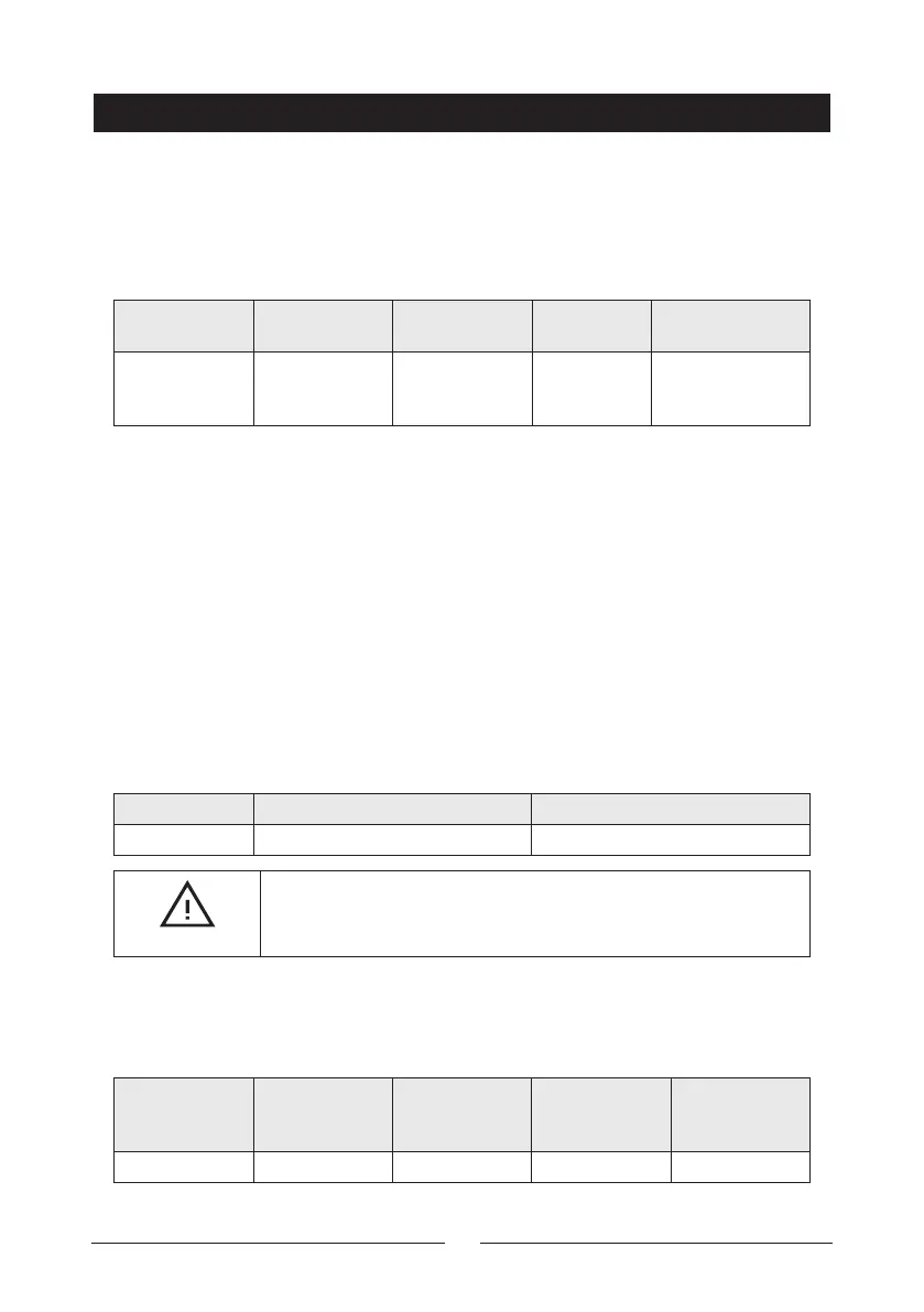
Model
Rated charge
current
Rated charge
power
Max. PV
power
Max. PV open
circuit voltage
MP3768 30A
390W/12V
780W/24V
580W/12V
1170W/24V
100V (lowest
temperature)
92V (25°C)
WIRE SIZE
The wiring and installation methods must conform to the national and local
electrical code requirements.
• PV wire size
The PV array’s output current varies with its size, connection method,
and sunlight angle. The minimum wire size can be calculated by its
ISC(short circuit current). Please refer to the ISC value in the PV module’s
specifications. When the PV modules are connected in series, the total ISC
is equal to any PV module’s ISC. When the PV modules are connected in
parallel, the total ISC is equal to the sum of all the PV module’s ISC. The PV
array’s ISC must not exceed the controller’s maximum PV input current.
For max. PV input current and max. PV wire size, please refer to the table as
below:
Model Max. PV input current Max. PV wire size
MP3768 30A 10mm
2
/8AWG
CAUTION
When the PV modules are connected in series, the total voltage
must not exceed the max. PV open circuit voltage at 25°C
environment temperature.
• Battery and Load wire size
The battery and load wire size must conform to the rated current, the
reference size as below:
Model
Rated charge
current
Rated
discharge
current
Battery wire
size
Load wire size
MP3768 30A 30A 10mm
2
/8AWG 10mm
2
/8AWG