16
INSTALLATION:
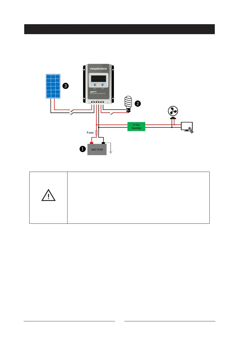
Step 2: Connect the system in the order of battery - load - PV array
following Figure 2-2, " Schematic Wiring Diagram," and disconnect the
system in the reverse order.
Figure 2-2 Wiring Diagram
CAUTION
• Please do not close the circuit breaker or fuse during the
wiring and ensure that the leads of "+" and "-" poles are in the
correct polarity.
• A fuse whose current is 1.25 to 2 times the controller's rated
current must be installed on the battery side with a distance
from the battery no longer than 150 mm.
• If an inverter is to be connected to the system, connect the
inverter directly to the battery, not to the load side of
the controller.