Additional UPS Features
26
Powerware
®
5115 Tower UPS (500–1400 VA) U ser’s Guide S 05146640 Rev C www.powerware.com
Table 1. DIP Switch Settings
120V Models
Output Voltage Input Voltage
Range
DIP Switch 1 DIP Switch 2
110V 99V-116V ON OFF/ON
120V* 108V–127V* OFF OFF/ON
230V Models
Output Voltage Input Voltage
Range
DIP Switch 1 DIP Switch 2
220V 198V–233V ON OFF
230V* 207V–243V* OFF OFF/ON
240V 216V–254V ON ON
*Default position
Communication Options
The UPS is equipped with a USB and a DB-9 communication port. Either
the USB port or the DB-9 communication port may be used to monitor
the UPS; however, they cannot operate simultaneously.
USB Port
The UPS can communicate with a USB-compliant computer using LanSafe
Power Management Software (v5.0.1 or higher). To establish
communication between the UPS and a computer:
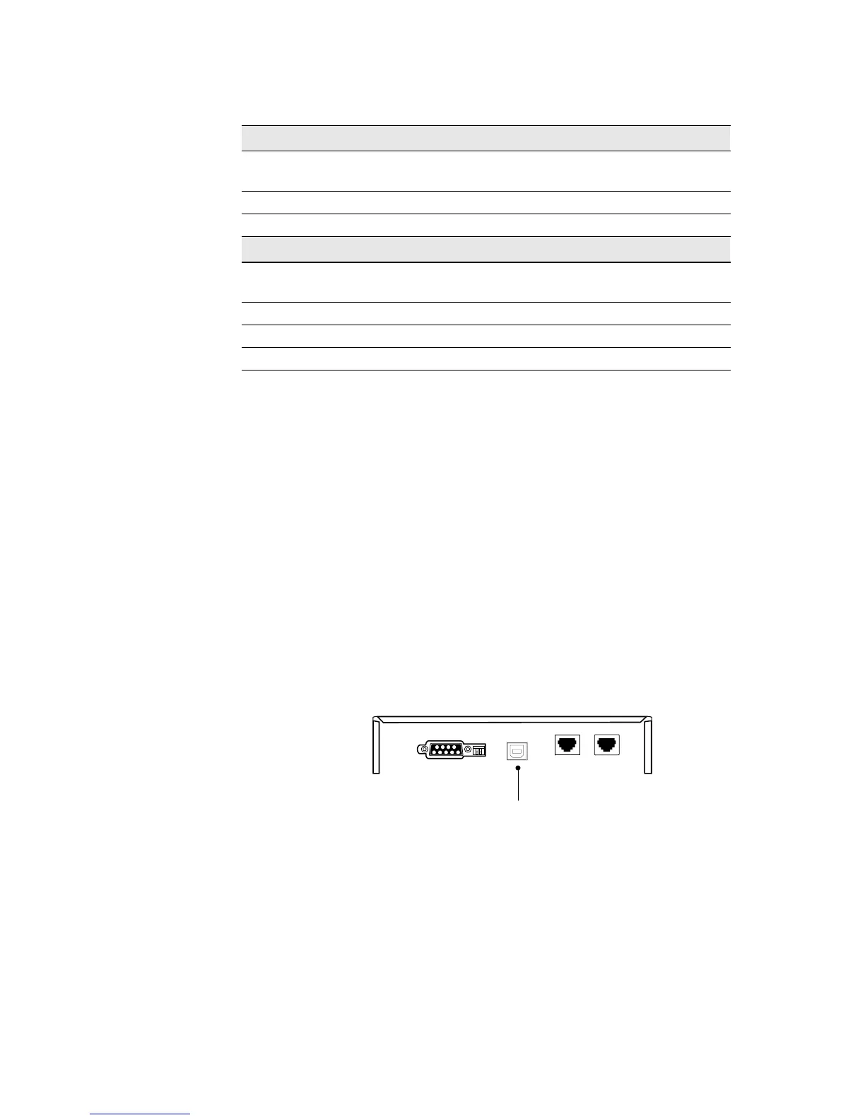
1. Connect the USB cable to the USB port on the UPS r ear p anel.
Connect the other end of the USB cable to the USB port on
your computer.
USB Port
Figure 13. The USB Port
2. Install the LanSafe software and USB drivers according to the
instructions provided with the Powerware Software Suite CD.