Additional UPS Features
28
Powerware
®
5115 Tower UPS (500–1400 VA) U ser’s Guide S 05146640 Rev C www.powerware.com
Network Transient Protector
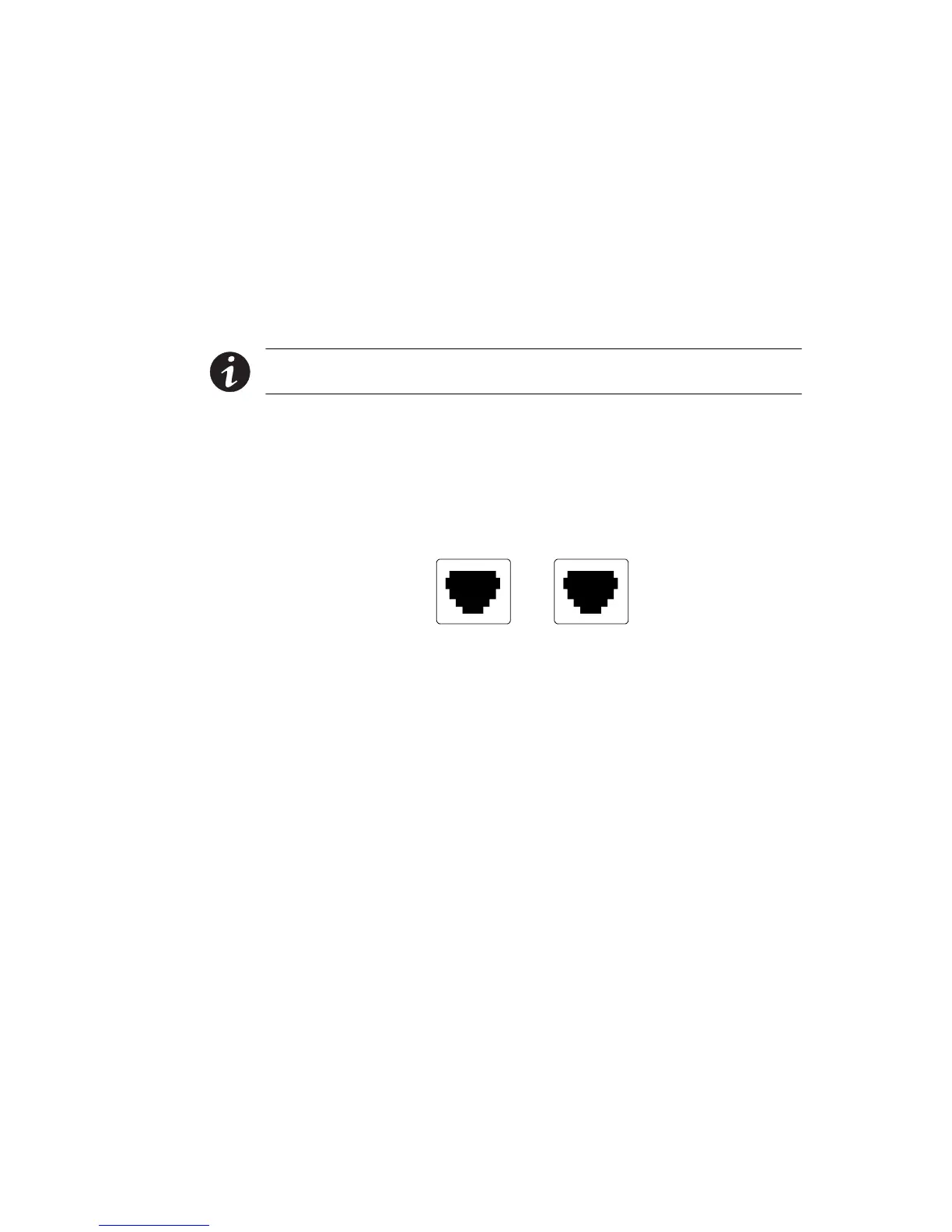
The Network Transient Protector, shown in Figure 15, is located on the
rear panel and has jacks labeled IN and OUT. This feature accommodates
a single RJ-45 (10BaseT) network connector.
Low voltage models can also accommodate an RJ-11 telephone
connector that provides protection for modems, fax machines, or other
telecommunications equip ment. As with most modem equipment, it is
not advisable to use this jack in digital PBX (Private Branch Exchange)
environments.
NOTE DO NOT connect any telephone or fax/modem equipment to the
230V models; only network protection is available for 230V models.
1. Connect the input connector of the equipment you are
protecting to the jack labeled IN.
2. Connect the network or telephone cable (low voltage models
only) to the jack labeled OUT.
OUT IN
IN
OUT
NETWORK TRANSIENT PROTECTOR
Figure 15. Network Transient Protector