Additional UPS Features
27
Powerware
®
5115 Tower UPS (500–1400 VA) U ser’s Guide S 05146640 Rev C www.powerware.com
DB -9 Communication Port
To establish communication between the UPS and a computer, connect
your computer to the UPS communication port using the supplied
communication cable.
When the communication cable is installed, power management s oftware
canexchangedatawiththeUPS.ThesoftwarepollstheUPSfordetailed
information on the status of the power environment. If a power
emergency occurs, the software initiates the saving of all d ata and an
orderly shutdown of the equipment.
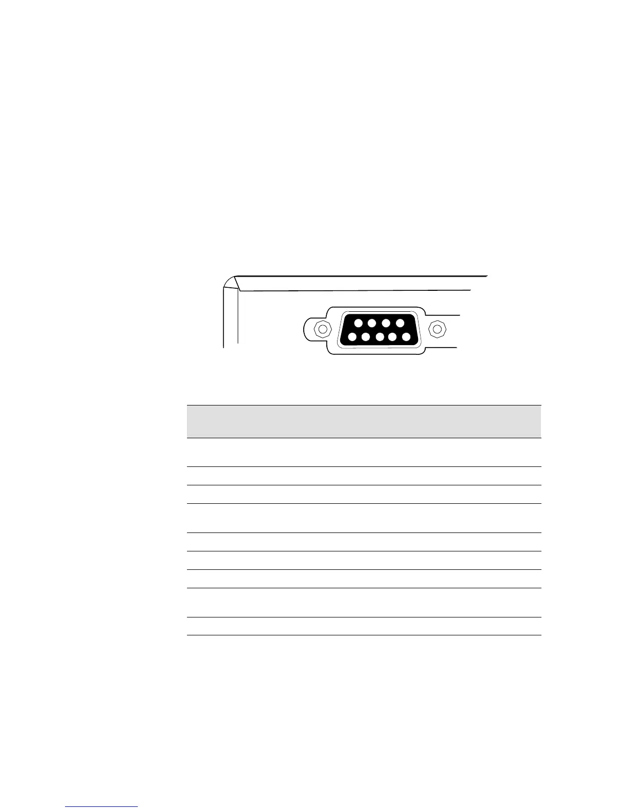
The cable pins are identified in Figure 14 and the pin functions are
described in Table 2.
3
8
7
9
1
6
245
UPS Rear Panel
Figure 14. Communication Port
Table 2. Communication Port Pin Assignment
Pin
Number
Signal Name Function Direction
from the UPS
1 Low Batt Low Battery relay contact; 20 mA,
30 Vdc contact rating
Out
2 TxD Transmit to external device Out
3 RxD Receive from external device In
4 DTR PnP (Plug and Play) from external
device (tied to Pin 6)
In
5 GND Signal common (tied to chassis) —
6 DSR To external device (tied to Pin 4) Out
7 — No Connection —
8 AC Fail AC Fail relay contact; 20 mA, 30 Vdc
contact rating
Out
9 Power Source +V (8 to 24 volts DC power) Out