Using Features and Options
6−6
EATON Powerware
®
9315 UPS (200–300 kVA) Operation Manual S 164201036 Rev G www.powerware.com
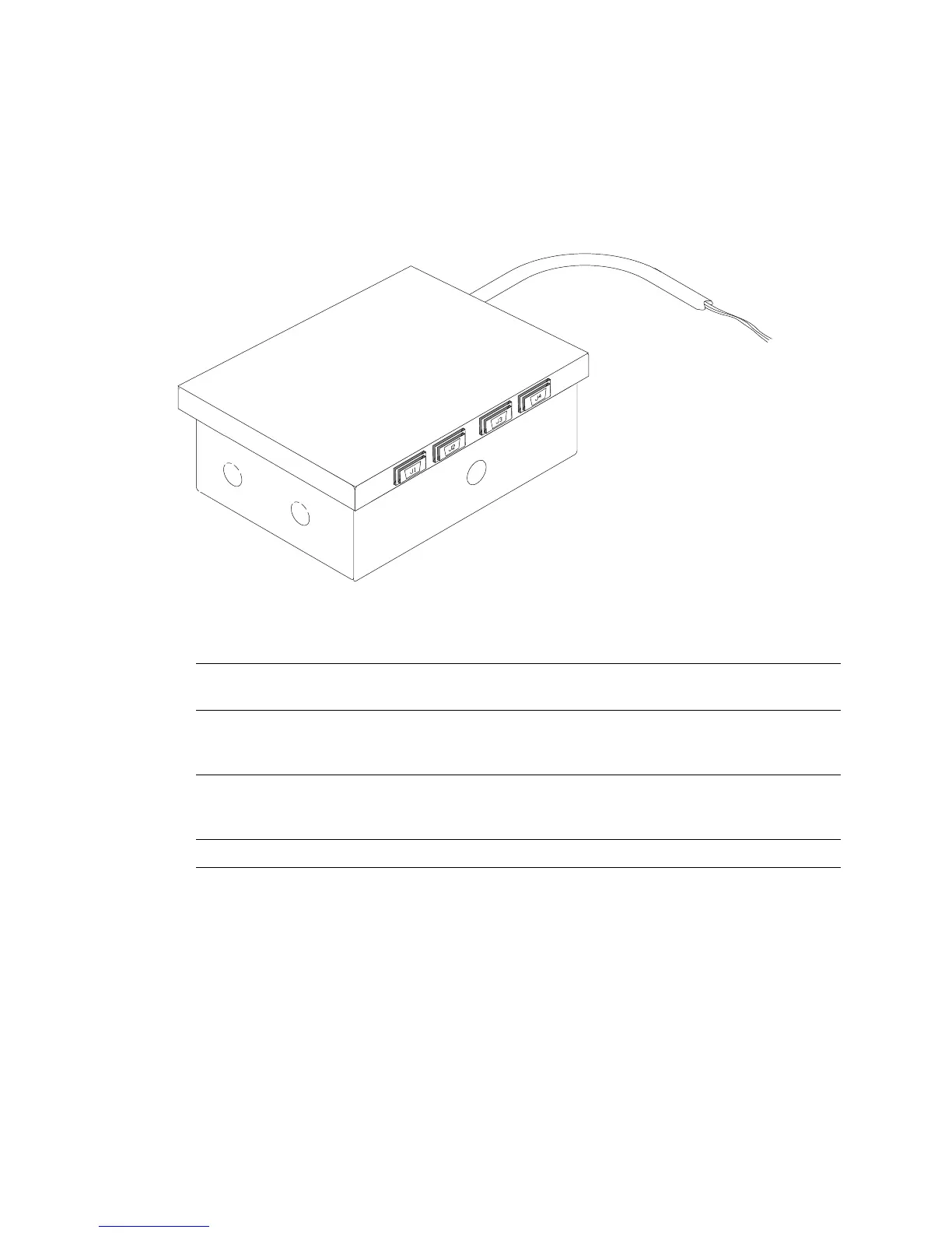
6.6 Relay Interface Module
An optional RIM uses relay contact closures to indicate the operating status and alarm
condition of the UPS system. A maximum of two monitoring accessories (RMPs, RIMs, or
SCMs) can be installed. See Table 6-1 on page 6−4 for the number of accessories
permitted. Figure 6-4 shows the RIM with its four 15-pin connectors labeled J1 through J4.
Figure 6-4. Relay Interface Module
The RIM can provide the following signals:
UPS AVAILABLE
Pins 1 and 12 Contacts are closed when the UPS is operating in
Normal mode or ready to supply the load.
UPS OFF LINE
Pins 3 and 13 Contacts are open when the UPS is offline.
Contacts are closed when the UPS is operating in
Normal mode.
BATTERY WEAK
Pins 5 and 14 Contacts are closed when approximately two
minutes of battery time is remaining, before the
critical load is lost.
UTILITY FAILURE
Pins 6 and 15 Contacts are closed when Utility Failure is detected.