+
-
+
-
+
-
Tx
+
-
31 32
41 42 43 44 45 4641 42 43 44 45 4641 42 43 44 45 46
41 42 43 44 45 46 41 42 43 44 45 46 41 42 43 44 45 46
41 42 43 44 45 46 41 42 43 44 45 46
+
-
mA
11 12
R2
R1
21 22 23 24 25 26
I+
Gnd.
11
12
31
32
CPU
AD
EEPROM
0.2 mA
PTC
20 Ω
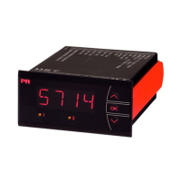
5714
1 2 3 4
46
45
44
43
42
41
TC+V
4 3 2
21
22
23
24
25
26
R1
R2
1
3
2
Tx
+
+
+
mA
36
37
CONNECTIONS
RTD,2-wire RTD,3-wire RTD,4-wire
PotentiometerVoltage
TC 2-wiretransmitter Current
Current Relays
Inputs:
Output:
Supply:
I
Output
Common
Relay 1 N.O.
Relay 1 N.C.
Common
Relay 2 N.O.
Relay 2 N.C.
Supply
Supply
21.6...253 VAC
or
19.2...300 VDC
Version D
Int.
CJC
2-wiresupply
> 15 VDC
Input +,
mA
Input gnd.
RTD,
wires
Potm.
BLOCK DIAGRAM
Readoutathardwareerror
Error search Readout Error cause
Test of internal communication uC / ADC HW.ER Permanent error in ADC
Test of internal CJC sensor CJ.ER CJC sensor defect
Check-sum test of the configuration in RAM RA.ER Error in RAM
Check-sum test of the configuration in EEPROM EE.ER Error in EEPROM
! Error indications in the display blink once a second. The help text explains the error.