Sensor error detection:
Programmable............................................. 3.5...23 mA
NAMUR NE43 Upscale............................... 23 mA
NAMUR NE43 Downscale........................... 3.5 mA
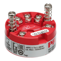
Ex data:
Signal output / supply, terminal 1 to 2:
U
i
................................................................. : 30 VDC
I
i
.................................................................. : 120 mADC
P
i
................................................................. : 0.84 W
L
i
................................................................. : 10 µH
C
i
................................................................. : 1.0 nF
Sensor input, terminal 3, 4, 5 and 6:
U
o
............................................................... : 9.6 VDC
I
o
................................................................. : 28 mA
P
o
................................................................ : 67 mW
L
o
................................................................ : 35 mH
C
o
................................................................ : 3.5 µF
EEx approval CENELEC:
DEMKO 99 .................................................. ATEX 126965
ATEX .......................................................... 0539 II 1 G
EEx ia IIC T1...T6
Max. amb. temperature for T1...T4............. 85°C
Max. amb. temperature for T5 and T6 ....... 60°C
Applicable in zone....................................... 0, 1 or 2
FM............................................................... IS, CL. I, DIV. 1, GP. A-D
Entity, FM Control Drawing No. ................. 5300Q502
CSA............................................................. Class I, Zone 0/1, Group IIC
Installation Drawing No............................... 533XQC03
Observed authority requirements: Standard:
EMC 89/336/EEC, Emission ....................... EN 50 081-1, EN 50 081-2
Immunity ....................... EN 50 082-2, EN 50 082-1
Emission and immunity ....................... EN 61 326
ATEX 94/9/EC.............................................. EN 50 014 and EN 50 020
Factory Mutual, ASCN ................................ 3600, 3810, 3611, 3610
CSA, CAN / CSA......................................... E79-15, E79-11
Of span = Of the presently selected range
23
Cable resistance per wire (max.)................. 5 Ω
Sensor current............................................. Nom. 0.2 mA
Effect of sensor cable resistance
(3- / 4-wire).................................................. < 0.002 Ω/Ω
Sensor error detection ................................ Yes
Short circuit detection................................. If 0% > 30 Ω
TC input:
Cold junction compensation....................... < ±1.0°C
External CJC with Ni100 or Pt100.............. -40 ≤ T
amb.
≤ 135°C
Sensor error detection ................................ Yes
Sensor error current:
When detecting.................................... Nom. 33 µA
Else ...................................................... 0 µA
Short circuit detection................................. If 0% > 5 mV
Voltage input:
Measurement range.................................... -800...+800 mV
Min. span..................................................... 2.5 mV
Input resistance........................................... 10 MΩ
Current output:
Signal range ................................................ 4...20 mA
Min. signal range......................................... 16 mA
Updating time.............................................. 440 ms
(660 ms for diff.)
Fixed output signal...................................... Between 4 and 20 mA
Output signal at EEprom error.................... ≤ 3.5 mA
Load resistance........................................... ≤ (V
supply
- 8) / 0.023 [Ω ]
Load stability............................................... < ±0.01% of span / 100 Ω
22
Type
Min.
temperature
Max.
temperature
Min.
span Norm
B
E
J
K
L
N
R
S
T
U
W3
W5
+400°C
-100°C
-100°C
-180°C
-100°C
-180°C
-50°C
-50°C
-200°C
-200°C
0°C
0°C
+1820°C
+1000°C
+1200°C
+1372°C
+900°C
+1300°C
+1760°C
+1760°C
+400°C
+600°C
+2300°C
+2300°C
100°C
50°C
50°C
50°C
50°C
50°C
100°C
100°C
50°C
50°C
100°C
100°C
IEC584
IEC584
IEC584
IEC584
DIN 43710
IEC584
IEC584
IEC584
IEC584
DIN 43710
ASTM E988-90
ASTM E988-90
 Loading...