13
PM-833TV 4-13-21V1.indd Copyright © 2021 Quality Machine Tools, LLC
CHANGING HEADSTOCK ELEVATION (Z-AXIS)
The headstock is raised and lowered by the hand crank,
Figure 3-8. The crank handle disengages from the lead-
screw by spring action. Press the handle in to engage.
Before moving the headstock, be sure that:
1. The exible oil line to the headstock is tucked inside
the column, Figure 2-1.
2. The clamp levers have been loosened, Figure 3-7.
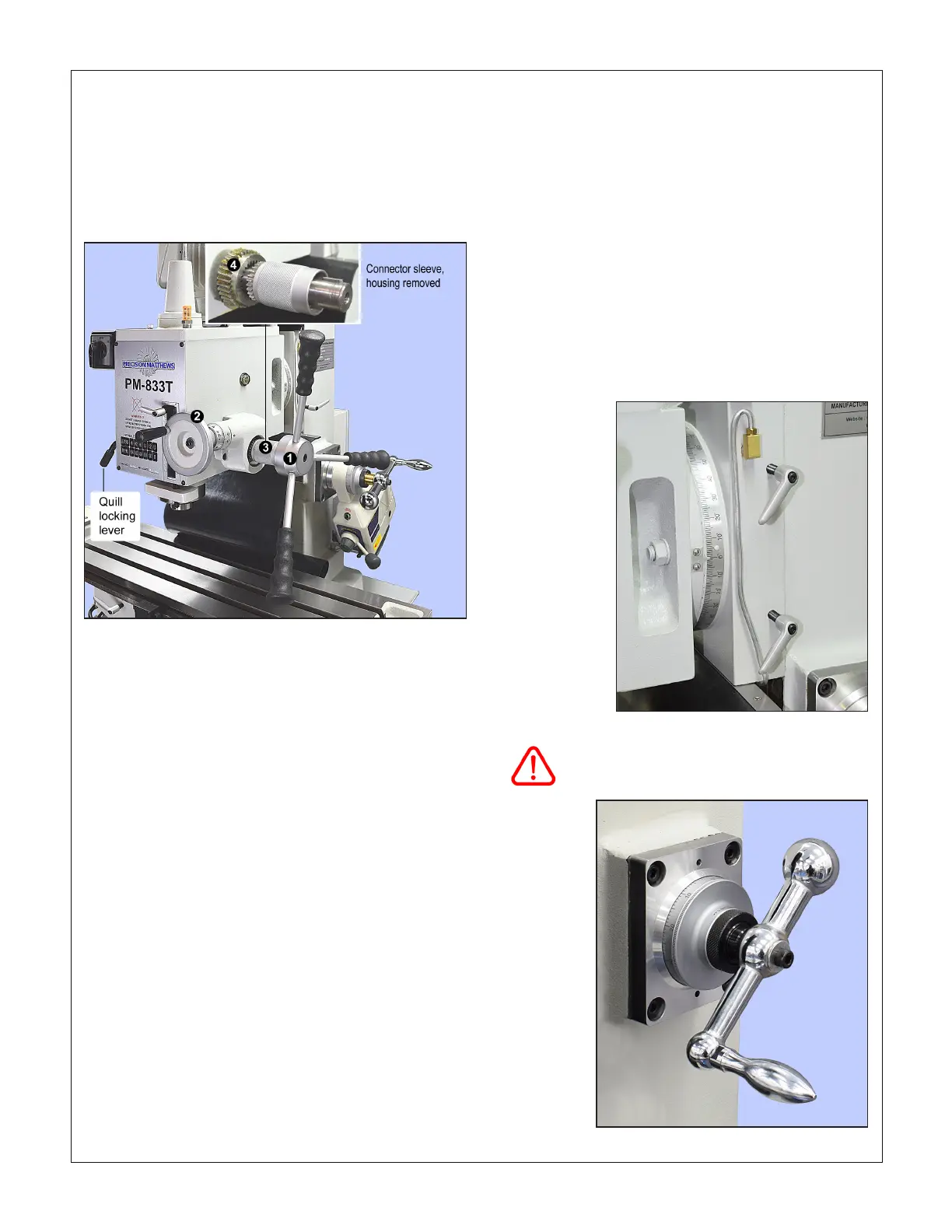
QUILL DOWNFEED
The quill is controlled in two dierent ways, coarse and
ne, Figure 3-6.
In the drilling mode, coarse feed, the mill functions like
a standard drill press — lower the quill using any of the
three downfeed levers to rotate the lever hub count-
er-clockwise.
Figure 3-6 Quill downfeed controls
(File photo PM-833T) Lever hub (1) is full-time connected to the pinion
shaft controlling the quill rack. The ne control handwheel (2) drives
worm gear (4), which is free to rotate — doing nothing to the quill —
unless it is coupled to the pinion shaft by connector sleeve (3). Teeth
on the knurled sleeve, which is keyed to the pinion shaft, mesh with
inner teeth on worm gear (4).
Coarse feed
For drilling operations, slide the knurled connector
sleeve to the right. If desired, set the depth stop, Figure
3-1.
Fine feed
For milling operations calling for precise, repeatable
control of tool depth, slide the knurled connector sleeve
left to engage the ne-feed worm gear.
Rotate the ne control handwheel to raise or lower the
quill. Before switching to ne control, it is usually a good
idea to run the depth stop up to the top. Lower the quill
by turning the handwheel clockwise, positioning it pre-
cisely by counting divisions on the graduated dial.
If you are counting divisions be aware of backlash in
the worm drive. This means that the handwheel must
always be turning in the same direction throughout
the entire process, from setting a reference level to sub-
sequent cutting passes at specic depths.
Be sure to loosen the clamp levers before
moving the headstock, especially under
power
Figure 3-7 Headstock clamp levers
Bear in mind that the quill is spring-loaded. This calls for
care when releasing the quill locking lever prior to repo-
sitioning the quill downward. If the ne control knob has
been allowed to disengage (backed o counter clock-
wise), the quill will jump up by 0.01” or more. To avoid
this, make sure the ne control is rmly clockwise, lightly
loading the quill rack, before releasing the locking lever.
Figure 3-8 Headstock adjust handle

 Loading...
