16
PM-833TV 4-13-21V1.indd Copyright © 2021 Quality Machine Tools, LLC
X & Y-AXIS POSITIONING BY COUNTING
DIVISIONS
For all spindle positioning operations, with or
without DROs, avoid using the quill lock. Retract
the quill fully, then adjust the headstock elevation
instead.
Why? On practically all vertical mills, including the heavi-
er knee mills, locking the quill may oset the spindle by a
few thousandths of an inch. If the edge of the workpiece
has been “found” in the quill-locked condition, this will af-
fect placement of holes drilled thereafter. Instead, lower
the quill with the ne downfeed control. This is worm
driven, so it stays where it’s put without locking.
Note: This does not apply to operations calling for pre-
cise depth control, such as milling. For such operations
the quill must be locked to maintain a given depth of cut.
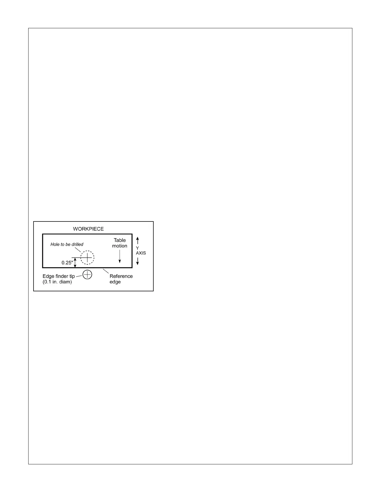
Figure 3-15 is an example of Y-axis positioning by count-
ing dial divisions. A hole is to be drilled 0.25” back from
the front edge of a workpiece in a vise, or otherwise
clamped to the table.
1. Install an edge-nder in collet or chuck (a tip diame-
ter of 0.2” is assumed).
2. Lock the X-axis by tightening the clamp levers (op-
tional).
3. If the reference edge is already to the back of the
spindle centerline, do nothing; if not, rotate the Y-axis
handwheel clockwise to send the workpiece back-
wards (toward the column).
4. Engage the ne downfeed.
5. With the spindle running, lower the quill as necessary
using the ne downfeed handwheel; bring the table
slowly forward (counter-clockwise), stopping at the
point where the edge-nder just makes contact with
the workpiece — the tip will jump out of line. Stop the
spindle.
6. While holding the Y-axis handwheel to prevent any
movement, zero the dial.
7. Raise the quill, then rotate the handwheel exactly
one full turn counter-clockwise (0.1”) to bring the
reference edge forward to the spindle centerline.
Figure 3-15 Spindle positioning example
8. Rotate the handwheel counter-clockwise an addi-
tional 2-1/2 turns to bring 50 on the dial opposite the
datum; the spindle is now 0.25” behind the reference
edge, ready for drilling.

 Loading...
