17
PM-833TV 4-13-21V1.indd Copyright © 2021 Quality Machine Tools, LLC
TILTING THE HEADSTOCK
In routine operations, the user relies on squareness of
the spindle relative to both axes of the table. Front-to-
back squareness set at the factory, and is not adjustable
(by everyday methods), but in the other plane the head-
stock can be set to any angle up to 90 degrees either
side of the normal vertical position. [Because re-estab-
lishing true vertical – tramming — on any mill is a time
consuming process, most machinists look rst for other
ways of handling the project instead of tilting the head.]
The headstock is secured by three nuts spaced 120 de-
grees apart, one underneath and one either side, Fig-
ure 3-16. The headstock is top-heavy, and may swing
suddenly to either side unless a helper is on hand to
restrain it. Using a 19 mm wrench, testing for movabil-
ity as you go, carefully loosen the nuts by degrees. Be
especially careful if the head has not been moved be-
fore, because the paint seal may let go without warning.
(First-time tilting may also call for unusual eort on the
wrench.)
Set the headstock to the desired angle by reference to
the tilt scale, then re-tighten the nuts. Bear in mind that
this is good only to approximately ± 0.25
o
, so a more
accurate means of angle measurement will be needed if
the project calls for precise tilting.
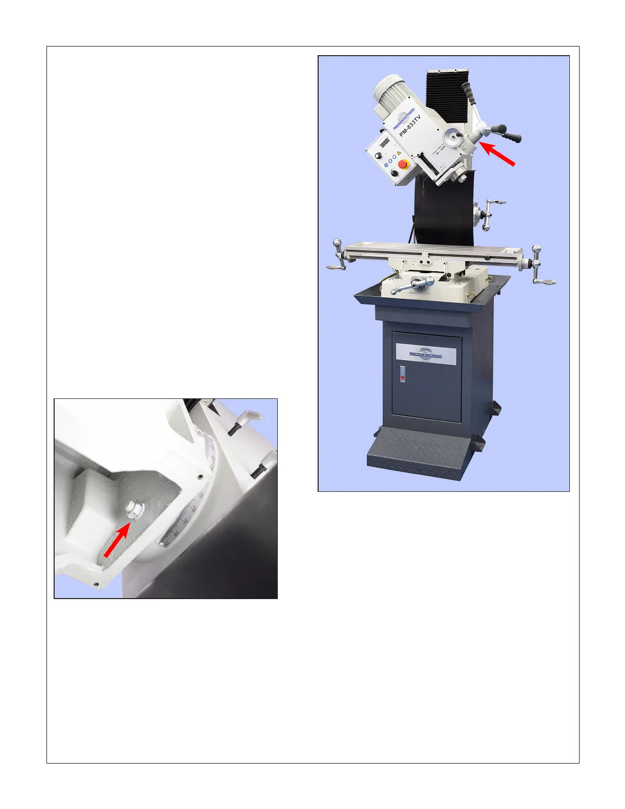
Figure 3-17 Headstock tilted 45
o
counter clockwise
The knurled connector sleeve, arrowed, tends to slide down-
ward, possibly meshing with the ne downfeed gear, Figure
3-4. This will disable the quill levers (coarse downfeed). If this
is undesirable, tape the sleeve temporarily to the lever hub.
Figure 3-16 One of three headstock attachment nuts
Remove the bottom cover for access. The other two nuts are in pock-
ets on the sides of the headstock casting..

 Loading...
