25
PM-833TV 4-13-21V1.indd Copyright © 2021 Quality Machine Tools, LLC
The following 6 pages are standalone instructions
for power feed installation. Figure numbers are not
in sequence with earlier pages of Section 4.
INSTALLING THE TABLE POWER FEED
The Precision Matthews Table Power Feed kit is specically
engineered for the PM-833TV mill, Figure 1. Power required
is 110V, 60 Hz.
Figure 1 Table (X-axis) Power Feed unit
Installation of the table power feed is straightforward, calling
for standard shop tools such as a power drill, plus two sizes
of metric taps: M5 and M8.
Kit contents
• Motor unit
• Mounting bracket
• One 3 x 15 mm key
• Gear (for leadscrew), Figure 3
• Gear cover, Figure 7
• M8 hex head screws (mounting bracket to table)
• M6 screws (motor to mounting bracket)
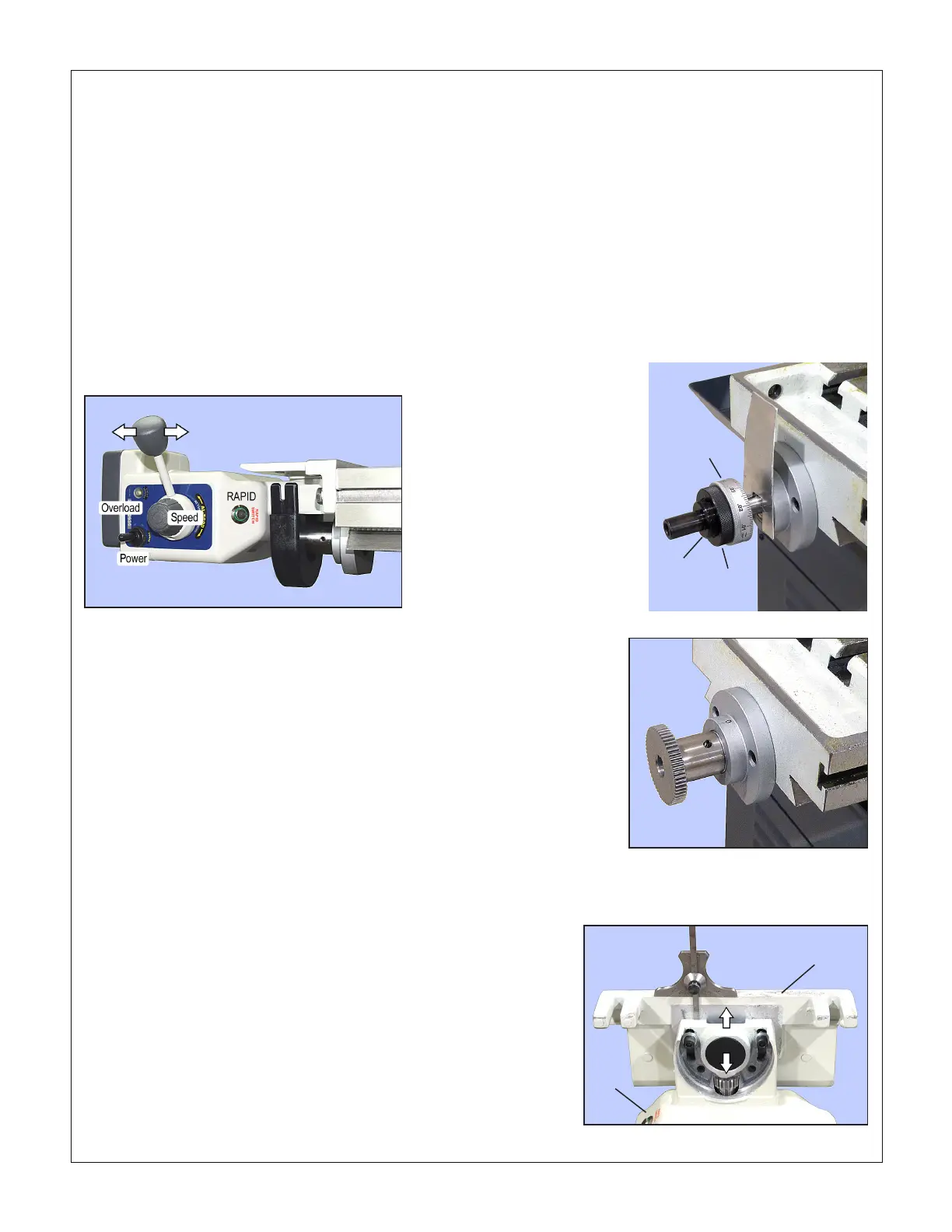
Figure 2 Remove LH
end components
If you need to use pry
bars — such as a pair of
at-blade screwdrivers
— protect the bearings
and ange with scrap
metal, not supplied. None
of these components is
reused when the power
feed is installed.
Dial
Knurled
ring
Threaded
bushing
Figure 3 Install gear on leadscrew
Leave a small gap, 0.010" or so, between
gear stem and the outer bearing
Motor
unit
Mounting
bracket
Figure 4 Align the motor and mounting bracket
POWER FEED OPTIONS
Servicing the power feed motors
There are two carbon brushes on each power feed mo-
tor. If removed for inspection, they should be replaced in
the same orientation. Replace both when worn down to
about 0.2”.
Suggested procedure
1. Remove all components from the left hand end of the lead-
screw, Figure 2.
2. Install the gear, with key, on the leadscrew, Figure 3. Leave
clearance between gear stem and the leadscrew outer
bearing. Tighten the set screw.
3. Attach the motor unit to the mounting bracket, Figure 4,
leaving the two M6 screws loose enough to allow the
bracket to slide fore and aft relative to the motor (slots in
the head casting).
4. Set the mounting bracket against the left hand end of the
table. Position the motor so that, looking from below, the
small motor gear is aligned with the gear on the leadscrew,
100% meshing. Tighten the two M6 screws enough to pre-
vent accidental repositioning, then set the motor vertically
on the bench.
5. For accurate alignment of the two gears — this is import-
ant — the mounting bracket must be at right angles to
the motor axis. This can be approximated by aligning the
bracket with the motor head casting (use a depth gauge,
as Figure 4, or other means). Proper alignment minimiz-
es gear noise!
6. With the assembly back in place against the mill table,
check again for mesh. Readjust if necessary, then fully
tighten the M6 screws.
7. Position the motor/bracket assembly centrally relative to
the leadscrew gear — small gear directly in line above the
larger gear. Mark the table to show the two bracket slot
locations, Figure 5.
8. Drill and tap M8 holes in the two locations. Install the two
M8 screws and washers supplied.

 Loading...
