26
PM-833TV 4-13-21V1.indd Copyright © 2021 Quality Machine Tools, LLC
Figure 5 Drilling layout
The dimensions shown are approximate. Measure the
mounting bracket that came with your kit to be sure.
3/4"
6-3/4"
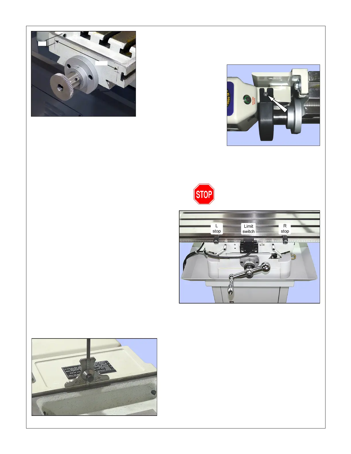
9. Grease the leadscrew gear, then cover it with a narrow
strip of scrap printer paper (about 0.004" thick). This is for
the correct separation between motor gear and leadscrew
gear.
10. Set the motor assembly in position, then tighten the M8
screws. Adjust for an even margin across the width of the
mill table between tabletop and motor bracket, Figure 6.
11. Crank the leadscrew a few turns to eject the paper sep-
arator.
12. Crank the leadscrew 20 or so turns in both directions, lis-
tening for noises that may call for minor adjustments of
motor position.
13. Install the gear cover, Figure 7.
14. Remove and set aside the two stop blocks from the front
T-slot.
15. Install the limit switch assembly in place of the original stop
block casting, Figure 8.
16. Install L and R movable stops in the front T-slot.
17. Set the table to mid-travel, free to move (no obstructions,
clamp levers loosened). Install the knob on the table feed
motor control lever. Set the speed control fully count-
er-clockwise. Connect the motor unit to 110V ac power,
and switch on.
18. Set the direction lever to LEFT or RIGHT, then slowly rotate
the speed control to run the motor. (These are straight-cut
gears, so expect a moderate amount of gear noise.) Test
the stop switches by applying light nger pressure to the
Figure 6 Level the motor installation
Figure 7 Gear cover
The gear cover is held in place by foam sticky
pads (pre-installed), or by two button-head M5
screws, arrowed.
Figure 8 Limit switch & stop blocks
Movable L and R stop blocks, together with the limit switch assembly,
prevent over-travel when the table is power driven.
Allow the motor and table to stop
moving before changing direction
limit switches. If the table is moving left, for instance, pres-
sure on the left hand actuator should stop the motor.

 Loading...
