30
PM-833TV 4-13-21V1.indd Copyright © 2021 Quality Machine Tools, LLC
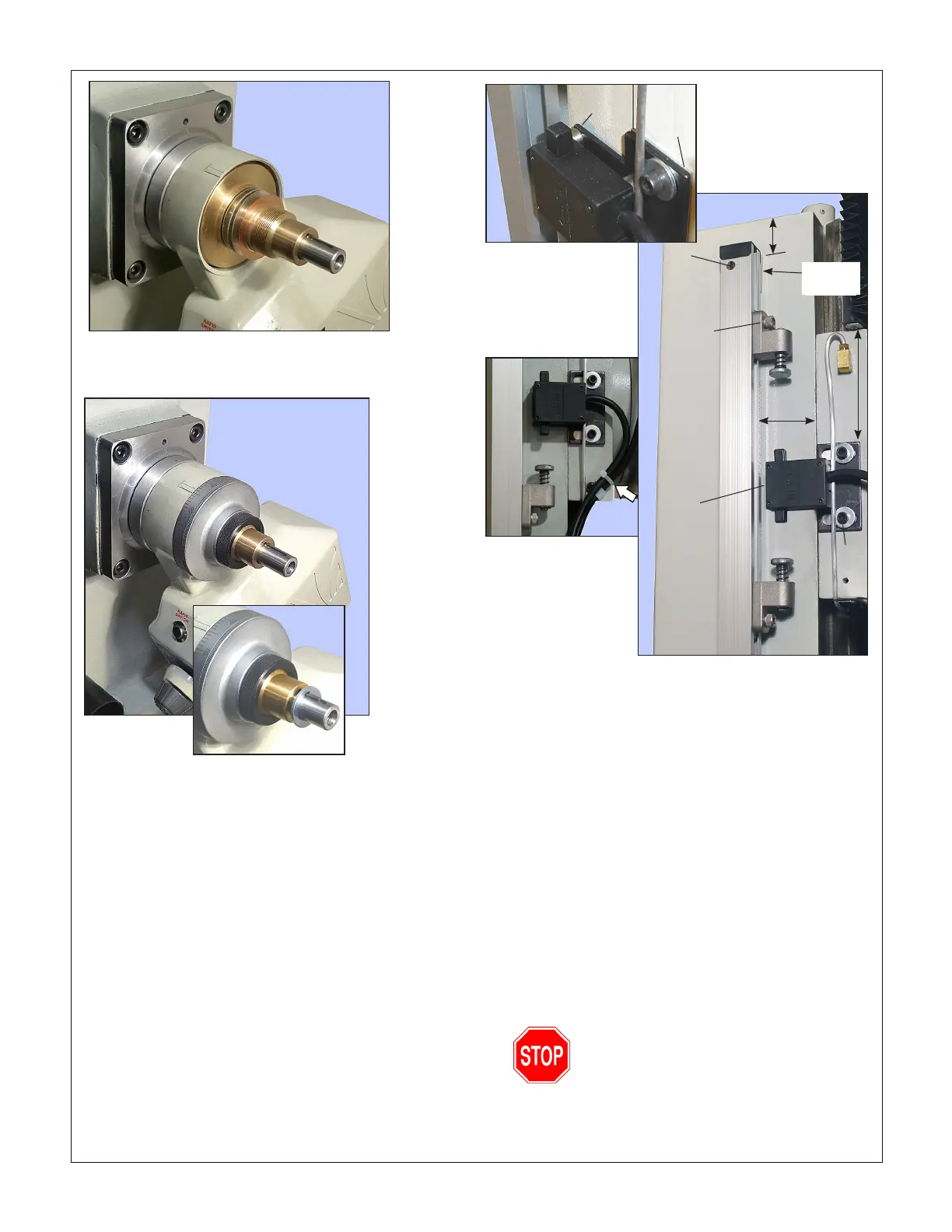
Figure 12 Dial re-installed
The spacer washer, inset, is for clearance be-
tween the crank handle and the motor body.
INSTALLING THE FEED STOPS
Figure 13 shows a suggested installation. The dimensions are
not critical.
Suggestion Cast iron powder gets everywhere! Before drill-
ing, protect all surfaces in the vicinity with taped-on scrap pa-
per. Before through-drilling into the column, remove: 1. The
accordion-pleated top cover, and; 2. The heavy nitrile cover
from the underside of the headstock, draping it forward over
the table. Protect the Z axis leadscrew, etc., before drilling and
tapping. Clean up with a vacuum.
1. Drill holes for M5 screws at top and bottom of the extrusion,
with oversize holes on the outer surface large enough for
the screw heads.
2. (Optional) In the installation shown in the photographs, the
limit switch mounting plate was shimmed by a 3 x 1-1/2"
aluminum plate 1/16" thick, drilled for two M6 screws. This
holds the mounting plate clear of the column, and also
Figure 13 Feed stop assembly
serves as a template for drilling the headstock.
3. To allow room for the aluminum oil pipe under the limit
switch cable, the limit switch was installed on 1/4" thick
stando bushings, Figure 13 inset. This called for longer
M3 screws than those supplied.
4. For better alignment of the limit switch actuators and the
feed stops, the extrusion was installed on 1-1/4" square
1/4" thick aluminum stando plates at top and bottom.
5. The lower inset, Figure 13, shows the limit switch cable tied
to the power cable.
6. For easier adjustment, the hex head 5/16-18 clamp screws
were replaced by socket head cap screws.
7. With the headstock at mid-travel, clamps loosened, pow-
er up the unit. Set the direction lever to UP, followed by
DOWN. Test the stop switches by applying light nger pres-
sure to the limit switches. If the headstock is moving down,
for instance, pressure on the lower actuator should stop
the motor.
Allow the motor and headstock to stop
moving before changing direction
1-1/2"
1.9"
M6
M5
5/16-18
clamp
screw
Limit
switch
4"
1/4" thick
stando
Stando
bushing
1/16"
shim
plate
Figure 11 Large shim washers on brass gear stem
Five washers were used on the sample machine: 3 x
0.024", 0.008" and 0.004".

 Loading...
